Links:
EPTS can also be used to measure the distance between two points on an image, with options to measure the distance in user space or graph coordinate space:
While there are many command-line options, mostly used to configure templates and scripts, there are some GUI-specific options that are used when EPTS is started by a window system. There are three EPTS-specific file formats as well:
epts. They provide the data needed to reconstruct
the background and the paths and points that were configured.
eptc. They provide EPTS
configuration data specific to a given session: information needed
to construct a saved-state file when scripting is used, additional
codebases needed for scripts, scripting-language variables that
can be set, and arguments that should be passed to
the java command used to start the Java virtual
machine (e.g., arguments to adjust the amount of memory allocated
to the JVM). Session-configuration files are generally not needed
for casual use.
eptt, and provide EPTS
configuration data for template processing. These files are an
alternative to providing a long series of command-line options.
make or ant.
Most of these options can by stored in EPTS saved-state,
session-configuration, and template-configuration files, and can be
set up by using various dialog boxes.
When a window system is used, it will tyically be configured to allow
a number of operations to be performed without using the command-line
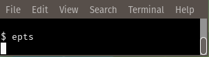
interface. For example, with the GNOME window system, when the user
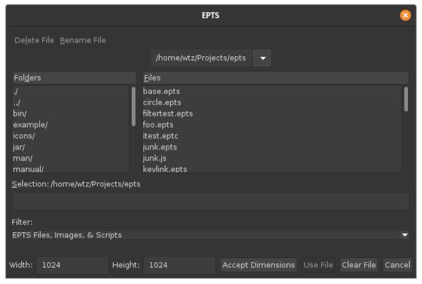
double-clicks the EPTS application's icon, EPTS will ask the user to
select a file: either an EPTS saved-state file, an EPTS
session-configuration file, an image in a recognized format (JPEG,
PNG, etc.), or a script file with recognized file extension (by
default, "js" and "es", although additional scripting languages may be
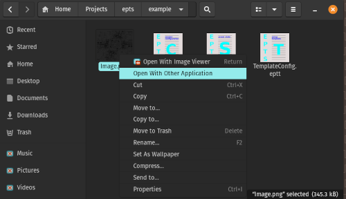
configured). When the mouse pointer is over the EPTS icon, and the
right mouse button is clicked, a list of "actions" that can be
selected will be shown:
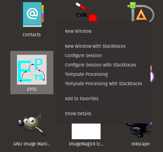
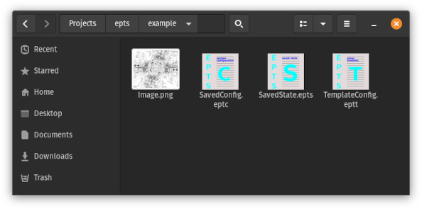
For the case of an image file, or when a saved EPTS file exists (one
whose extensions are eptc, epts, or
eptt), a GNOME file manager can be used to start EPTS. For
example, the following figure shows a file-manager window:
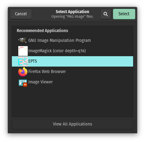
Select Application window
will appear:
scrunner command.
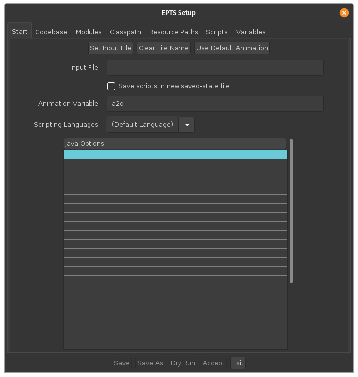
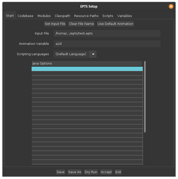
When the Configure Session desktop action is used, it will
display a dialog box. One will typically click on the
Set Input File button shown in the start pane
(the pane initially selected when the dialog box is displayed), and use
a file chooser to pick an image file. Alternatively one can type the
image-file name, or a URL, into the Input File field.
One can also add options supported by the java command.
org.bzdev.anim2d. Manuals describing this
software is listed in the
additional documentation section below.
Typically, one will want some animation objects as a background, and
will then use EPTS to create a series of paths. These will be written
to a file in a scripting-language compatible format. The scrunner
program can take multiple scripts as its arguments and will run those
scripts in the sequence specified, so it is easy to build up a script
from a series of files, some of which contain scripts generated by
EPTS.
For the simplest case, one can provide a script (e.g., written in ESP
or ECMAScript) and provide that script ESP's command-line
argument. The script should create an animation named a2d and use
factories or other mechanisms to create animation objects. These will
be displayed using the specified Z-order. The animation will not be
run so the object displayed are those that are initially visible. It
is safer to use ESP as a scripting language: the Nashorn script engine
was deprecated in Java 11 and removed in Java 15. ESP is provided as
part of the BZDev library, which EPTS uses.
To set up EPTS for more complex cases supporting animations, use the
Configure Session desktop action:
Save scripts in new saved-state file" is enabled. When
this checkbox is selected, the Acceptbutton will start
EPTS and configure it so that the scripts provided will be saved when
an EPTS file is created. This cannot be done with an image because GCS
has to be configured before the scripts are run. One may have to
select a scripting language if additional languages are available, but
the default, ESP, is always available and is the preferred choice. The
additional documentation section indicates were
to find documentation for ESP. The default value for the
scripting-language variable representing an animation
is a2d, but this can be changed if desired.
The next step is to bring up the Scripts pane using the tab
on the top of the of the dialog box, and insert names of the files
contains scripts that should be run in the table that makes up most of
this pane (these scripts are run in the order shown):
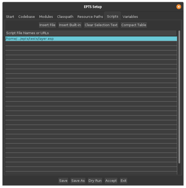
Insert File button can be used to display a file
chooser that will insert the selected file at the selected row in the
table. If scripting-language variables are needed, the
Variables pane can be used. This allows one to specify
the name of a variable, its type, its value, and units for the value
(units are used when the value is a real number). Some scripts can be
configured by a user, and allow the user to define various values to
control their appearance (for example, to set line thicknesses). Once
done, the final step is to optionally save the configuration and then
push the Continue button. EPTS will then close the
dialog box and open a window with the image the script created.
Regardless of what else is done (such as creating paths), one should
configure graph-coordinate space. The procedure is as follows:
ALT-I (do not use the shift key) to measure
a distance in units of points between two points whose "real world"
distance is known. The distance will be automatically copied to the
system clipboard.
File menu item Configure GCS
(or type the sequence ALT-F followed by
C) to open a dialog box for configuring
graph coordinate space.
User-Space Distance
text field.
OK button.
Save or
Save As menu items in the File menu.
Saved-state files must have the file-name extension epts.
To restart a saved sessions, run EPTS with the saved file as its argument or double-click on the saved-state file's icon in a file-manager window.
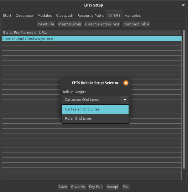
eptc
(e.g., test.eptc):
eptc
extension, the Scripts pane will be enabled and one can
use this pane to add scripts. The button Insert Built-in
will allow one to use predefined scripts:
Variables pane:
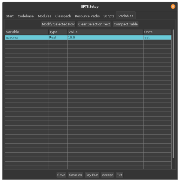
resource:grid uses a variable named spacing
to set the grid spacing. The type of the value is Read,
which provides some syntax checking for the value. When the value
represents a distance, the BZDev animation package and some related
class libraries use SI units, with distance measured in meters. One
can specify other units, feet in this example, and the
value will automatically be converted to meters before it is used.
The session-configuration should be saved if the configuration will be
used later. Such saved files must have the
extension eptc. To restart EPTS with a saved session
configuration, run EPTS with the session-configuration file as its
argument or double-click on the session-configuration file's icon in a
file-manager window.
One can configure templates by using the EPTS Template Processing
desktop action. This will open a dialog box containing six panes, only
the first of which will be enabled:
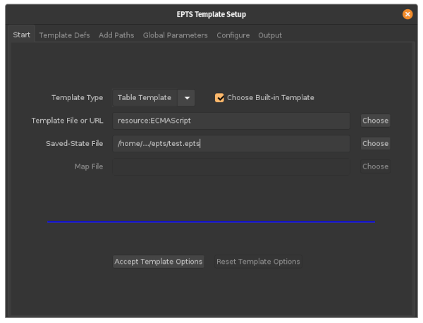
Start pane. One should first choose the
type of template out of the choices SVG,
Table Template, and PI Template (for
path-iterator template). One then can choose an appropriate template
(as long as the Choose Built-in Template checkbox is
checked, the Choose button next to the
Template File or URL text field will show templates of the
appropriate type). Neither this text field nor the checkbox are enabled
for SVG templates. One must also provide a saved-state file. The
Map File text field is used only for table templates
that use an atype directive (none of the built-in
templates use this directive). Once this data is entered, pushing
the Accept Template Options button will enable the
appropriate panes.
Template Defs pane. This pane is enabled
when the template is not a built-in template and allows one to define
additional directives that a user-provided template may need. The
table provided by this pane has three columns:
Test Directive. This is an iterative
directive with only one iteration and does not override or temporarily
add any directives. Text inside the iteration will appear once. It
is a conditional statement that is in effect when the directive's
value is not an empty string. The directive may, however, include
whitespace.
Directive. This defines a directive's name.
Value. This defines a directive's value.
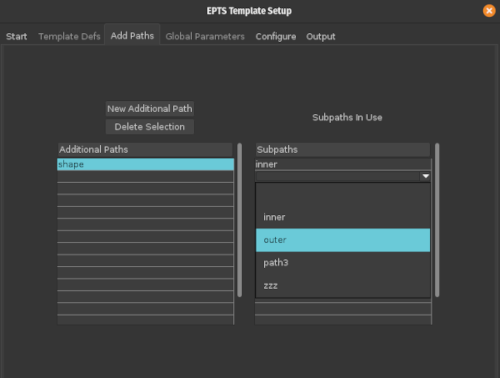
Add Paths pane. This pane initially displays
the paths defined by the saved state. One can add new paths that
are concatenations of these initially displayed paths. When a new
path is added, its list of subpaths will be empty. clicking on a
row in the subpath table will provide a menu with the names of the
subpaths that may be added:
Global Parameters pane. The use of this
pane is optional and the fields it displays are dependent on the
template type. It allows one to set a few directives or options.
Add Paths pane (the names of these paths are shown
using a bold font). There is a checkbox next to each
path and that checkbox should be selected for the paths that will
be included in the output. For table templates and the SVG template,
when a path is selected, various parameters for that path will be
displayed. For example,
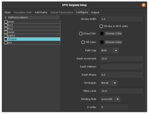
Stroke Width parameter and the
Stoke in GCS units checkbox will be used when
the DrawColor checkbox is selected and will be
ignored if this checkbox is not selected. Similarly, the remaining
parameters will be used when the Fill Color checkbox
is selected and will be ignored when this checkbox is not
selected. There are no parameters shown for locations. Those simply
provide an X and Y coordinate, and in an SVG file, are shown as a black
circle, surrounded with a white outline, and shown with white crosshairs.
Output pane. This option allows one to
choose an output file. There are also buttons for saving the
template configuration (the configuration file's file-name
extension must be eptt) and for generating output.
If the file name is "-", the output will appear on standard output.
This is an inappropriate choice when EPTS is started using a window
system as there is no terminal available to display the output. It is
useful if EPTS is started from the command line.
EPTS makes use of three coordinate systems, one indirectly:
org.bzdev.anim2d.AnimationLayer2DFactory (the
additional documentation section provides citations
to the documentation.
org.bzdev.graphs.Graph.
EPTS users should be familiar with several computer-graphics concepts when templates are used.
evenodd means that a point is
outside the curve's enclosed area if a line from the point to
infinity crosses the curve an even number of times and is
otherwise inside the curve's enclosed area. The
option nonzero computes the difference in the sums of
the number of times a line from a point to infinity crosses a
curve that turns counterclockwise and the of times a line from
that point to infinity crosses a curve that turns clockwise. If
this sum is zero, the point is outside the area and otherwise the
point is inside the area. At an intersection point, a curve turns
counterclockwise if it passes the line (pointing to infinity) from
right to left and is clockwise if it passes that line from left to
right.
SPLINE. Before being displayed, a sequence of
segments separated by knots will be converted to a sequence of
cubic Bézier curves, each with two intermediate control
points.
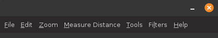
File menu.
Edit menu.
Zoom menu.
Measure Distance menu.
Tools menu.
Help menu.
File menu contains the following items:
Quit. Choosing this menu item causes the program to
exit.
Save. Choosing this menu item
causes the program to be saved. This option will request a file
name unless the first file-name argument is an EPTS saved-state
file.
Save As. Choosing this menu item causes the program to
be saved with a new file name. This new file will become the default
file name for the Save menu item.
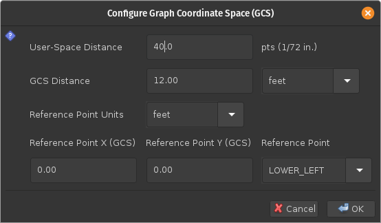
Configure CGS. Choosing this
menu item will open a dialog box for configuring graph coordinate
space. This dialog box allows one to set a distance in user-spaced
units and the corresponding distance in graph coordinate space
units. The units for graph coordinate space are either custom
units (arbitrary units defined by the user) or meters. If another
unit is specified, it's value will be converted to
meters. Canceling the dialog box will restore the values to those
that existed just before the dialog box was opened. Users may
specify a reference point (LOWER_LEFT,
LOWER_CENTER, LOWER_RIGHT,
CENTER_LEFT, CENTER, CENTER_RIGHT,
UPPER_LEFT, UPPER_CENTER, or
UPPER_RIGHT) and the graph-coordinate-space
coordinates for the reference point in either custom units or
meters. When explicitly configured, the coordinates for the
reference point will typically be (0.0, 0.0). When scripting is
used, The reference point is always set to LOWER_LEFT
and the reference point coordinates will be set to match the
coordinates used by the script. For example, when configuring EPTS
for an image, the dialog box shown below sets the scale factors so
that a distance of 40.0 in image space corresponds to a distance
of 12 feet (converted to meters) in graph coordinate space:
Print Table. Choosing this menu item will open
a 'print' dialog box to print the table.
Create Template. Choosing this item will start another
instance of EPTT configured to setup templates, using the current
instance's saved-state file. That saved state file must have been
created before this menu item is enabled.
Edit menu contains the following items:
Undo Point Insertion or Move. This
essentially removes the last row (two rows for a closed path) from
the table. If a previous path is extended via
the Edit menu's
Append to a Bezier Path item, that path will be
moved to the end of the table. While creating a path, this option
undoes the last change. The same is true when the menu item
Set Current Path/Location is used: the point or path
selected will be the last one in the table. There is one special
case: If a point along a path is selected and moved (either by
dragging the point, or using the keyboard's arrow keys), that
'move' operation can be undone provided that the 'undo' operation
occurs immediately (just clicking the mouse at a random point will
prevent a 'move' operation from being undone).
Append to a Bezier Path. This option
will extend a Bézier path. If one of a path's nodes has
been selected, that path will be extended. Otherwise a dialog box
will allow one to select the desired path. Existing specified
points along the path (spline knots, segment end points, and
intermediate control points) will be displayed using blue circles
to distinguish these from newly added points. The
Undo Point Insertion or Move menu item can be used
to delete newly added points, but not the existing ones shown in
blue, nor the path's initial point. Points can be added to the
path, and the path can be terminated, using the same operations
used when a path is newly created. For a closed path, the loop
must be broken for this menu option to be used.
Extend a Bezier Path. This option
will extend a Bézier path just as with the
Append to a Bezier Path menu item, but the
Undo Point Insertion or Move menu item can be used
to remove existing points on the path, not just the newly added
points. For a closed path, the loop
must be broken for this menu option to be used.
Move Location/Path. This option is used
to move a path or location using the mouse or keyboard. One will
select a control point (either before or after this option is selected),
and then drag the selected point. The operation will be completed
when the mouse button (the left mouse button) is released.
Alternatively, the keyboard's arrow keys can be used to
move the point one pixel at a time, ending a sequence of moves
by hitting the Enter key, or the Escape key if the operation should
be terminated. When the Escape key is used, the object selected will
be returned to its previous position.
Rotate Path. This option can be used to
rotate a path using the keyboard or mouse. One will select a
control on the curve (either before or after this option is
selected) and then drag the point (with the left mouse button
depressed) around the center of mass
of the path. The center of mass is shown by the intersection of
two principal axes drawn in orange.
The operation ends when the left mouse button is released.
Alternatively, one may use the arrow keys to indicate which way
the end of the first principal axis should move. The two principal
axes are shown and the longest one is the first principal axis.
When the keyboard is used, the operation ends with the Enter key
is hit to accept the change or the Escape key is hit to cancel the
operation.
Scale Path. This
option can be used to scale a path along its
principal axes. One will select a
control point on the curve and then drag the mouse. A red line
will indicate the amount of scaling, starting with a value of 1.0
in each direction. Each pixel (a unit of 1 point, actually)
represents an increment of 0.01. The principal axes will be shown
in orange, with their intersection point at the
center of mass for the path. Instead
of dragging the mouse, the keyboard can be used. In this case, the
left and right arrows decrease and increase the scaling along the
first principal axis by 0.01, and the up and down arrows increase
or decrease the scaling along the second principal axis by
0.01. Hitting the Enter key ends the sequence and hitting the
Escape key cancels the operation. If the shift key is pressed
while the arrow keys are used, both directions change
simultaneously by the same amount. When the mouse is used, the
behavior depends on the use of the control and shift keys:
Set Circle Divisor. This option opens a
dialog box that will allow one to chose an integer that determines
how many control points are used to draw a circle. Increasing the
number improves accuracy, but one will be hard pressed to distinguish
the difference visually.
Convert a Line to a Circle. This option applies
to paths that represent a single straight-line segment. It treats the
start of the line as the center of a circle and the end of the line
as a point on the circle. A path providing a very close approximation
to a circle will be drawn and the original line removed. The circle
will have the same name as the original line. Circles produced in this
way have a counterclockwise orientation. To get a clockwise orientation,
simply reverse the path by using the next item in the menu.
Insert an Arc into a Path. This option
inserts an arc into a selected point on a path. The segments
adjacent to that point must be straight-line segments, and for
open paths, the point must not start or terminate the path. A
dialog box will allow one to specify a radius in GCS coordinates,
the units for the radius, whether the arc should go clockwise
or counterclockwise relative to the path's direction, and
whether the selected point should be converted into a location
(in which case EPTS will ask for a new name). When a point
on a path has not been selected, this option will provide a hint
on the line just below the menus, and will ignore any points that
are are not part of the path. When a point (which is denoted by a
round black circle) has been selected, that point will be used,
but this option will be disabled if the point's adjacent segments
are not straight lines. One use of this option occurs when
specifying a path to be cut in a metal sheet—it can be used
to add "relief notches" at points where the metal should be bent.
If the selected points are converted into locations, those can be
used to draw lines representing where bends should occur.
Transform an Existing
    Path
. This option will scale, rotate, and/or
translate an existing path. The transformation is specified by a
dialog box. As with the previous operations,
the center of mass for the path and
its principal axes are shown. For
example, the following dialog box
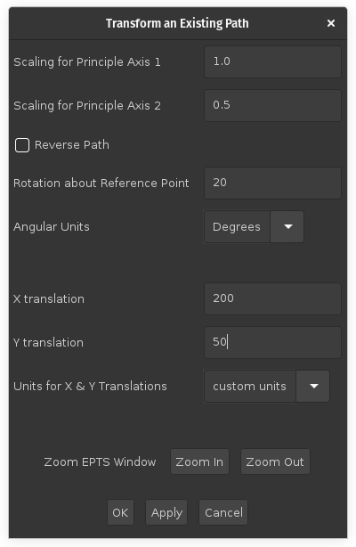
Reverse Path option
is not used in this example—when checked, it does not change the
path but does change the order in which the points along the path
are displayed in the table by listing the points in the reverse
order. Reversing a path is useful in cases where a
winding rule equal
to nonzero is used in cases in which paths are
concatenated (e.g., by using the --tname option), and
when a path is used in a animation or simulation as a path that
some object will follow (so that increasing the path parameter
moves a point along the path in the desired direction). If
the Apply button is clicked, a red shape will appear
showing the position of the transformed shape. The corresponding
EPTS window
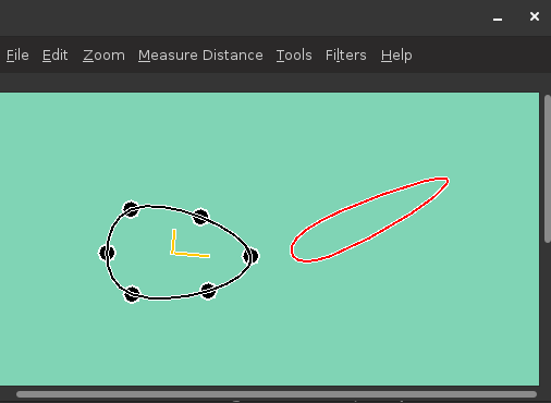
OK button
is pressed, EPTS will complete the operation. If the
Apply button is pressed, a bounding box showing
the new location The Cancel button will cancel this
operation. The EPTS window's controls are disabled while this
dialog box is visible. The dialog box, however, does provide
buttons allowing one to zoom in or zoom out. This dialog box
includes an option for reversing the path.
New Transformed Path.
This option's behavior is nearly identical to the
Transform an Existing Path option, but instead of
altering the original shape, a new one is added. EPTS will ask for
a new variable name.
Delete a Location / Bézier Path. This
option will delete a location or path. If a location or one of a path's
nodes has been selected, that location or path will be deleted. Otherwise
a dialog box will allow one to select the desired location or path.
Set Current Path/Location. Set the table so
that a specific path or location is the preferred one when
selecting points. When locations or control points from different
paths overlap, the most recently added path or location will be
preferred in resolving a conflict. This menu item makes a
specified path or location the most recently added path or
location. If there is no selected point, a dialog box will prompt
for a path or location by name. If there is a selected point, the
point or location associated with that choice is used to determine
the path or location's name. This option reorders the table
so that the selected path or location is at its end. Undoing the
last operation will then affect this path or location.
Copy table as ECMAScript or ESP. This option
copies the table to the clipboard after formatting it as a series
of ESP or ECMAScript statements (the syntax is identical in this
case).
Set the location format. This is a list of
radio buttons:
Location as (X,Y).
Location as x: X, y: Y}.
Location as {x: X, y: Y}.
Location as V = {x: X, y: Y};.
Drag-Image Mode. This menu
item determines if dragging the mouse drags the image. While one
can alternatively press the ALT key and then press the primary
mouse button, some window systems have shortcuts that process this
combination and do not pass it on to applications. The image will
not be dragged when this mode is in effect and a distance is being
measured or a path (or point) is being created or modified.
Zoom menu contains the following items:
Reset. This option resets the image size so that
one pixel on the image takes up one point on the screen, corresponding
to a zoom factor of 1.
Zoom In. This option increases the zoom factor by a
factor of 2 when the zoom factor is 1 or a multiple of either 2 or 1/2.
Zoom Out. This option decreases the zoom factor by a
factor of 2 when the zoom factor is 1 or a multiple of either 2 or 1/2.
Zoom To. This option sets the zoom factor to a
user-specified value.
Zoom In and
Zoom Out controls are disabled when the use of the control
would lead to a zoom factor outside of this range shown as explicit values
on the menu.
Measure Distance menu contains the following items:
Image-Space Distance. This option measures distances
in image-space units. This is particularly useful just before using
the File menu's Configure GCS option as the
value measured will be automatically copied to the clipboard and
can be pasted into the user-space-distance field which the
Configure GCS dialog box will show.
GCS Distance. This option measures distances in graph
coordinate space units. Until the File menu's
Configure GCS option is used, the ratio of GCS distances
to the corresponding image-space distances is 1 to 1.
GCS Path Length. This provides the total length
of a path in GCS units. If a path is not selected, a dialog box will
list the available paths. If a filter is installed, only the selectable
paths will appear. If a location is selected, the path length will be
0.
GCS Area. This provides the total area
of a path in GCS units. If a path is not selected, a dialog box will
list the available paths. If a filter is installed, only the selectable,
closed paths will appear. If an open path or a location is selected,
the area will be 0.
Tools menu allows points and curves to be created and
displayed in textual form. This menu contains the following items:
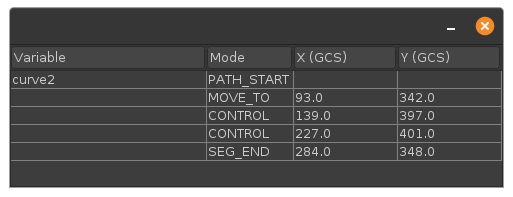
Show PointTable. Show a table containing
each location and curve, including the curve segments, with
control points for quadratic and cubic Bé segments and with
knots for spline segments. The only points
contained in this table are those created with a variable name.
All curves are included because all of the curves have a variable
name. As an example corresponding to
an example shown below, a table for a
cubic Bézier curve with two control points is the
following:
Edit Variable Parameters. Show a table listing
variable names for locations and paths, plus their key,
link, and description parameters. The variable
parameters can be edited, but not the variable names.
Set Arc-Angle
    Level
. This option allows the user to set the arc-angle
level. When circular arcs are drawn, multiple segments will be
used when the desired angle is larger than a limit. Four levels
are provided: Level 1 corresponds to a limit of 90 degrees, Level
2 corresponds to a limit of 45 degrees, Level 3 corresponds to a
limit of 22.5 degrees, and level 4 corresponds to a limit of 11.25
degrees. Circular arcs can be drawn by using
the Add Arc operation and
the Offset Path option
provided by this menu. The
Offset Path option will draw a circular arc only
when necessary.
Create a Point. This option will create a new,
isolated point. It will appear in the table if given a name.
A description of this point, in a format set by Edit
menu options, will be copied to the clipboard. Selecting an option
other than the one specifying a variable name will result in the
point not appearing in the table. If a variable name is requested
and the variable name is left as an empty string, a new variable
name will be generated, starting the string "pt" and followed by
a number (e.g., pt7.)
Create a Bézier Path. A new path will be
created. A dialog box will ask for a variable name for the path,
and the cursor will change to a cross-hair cursor, and the user
should select the initial point on the curve. The point type
shown in the table is MOVE_TO—only one such point
is allowed for each curve. If a variable name is requested and the
variable name is left as an empty string, a new variable name will
be generated, starting the string "path" and followed by a number
(e.g., path24.)
Offset Path. This
option will allow one to create offset paths by bringing up a
dialog box:
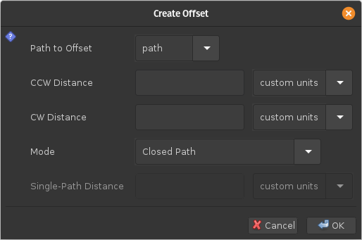
Path to Offset. A pull-down menu will allow
one to specify a reference path. There are paths associated with
the reference path: one in the counterclockwise direction when
proceeding along the reference path from its start to its end, and
the other in the clockwise direction. Where the reference path is
a smooth path, these additional paths are offset from the reference
path by specified distances.
CCW Distance. The distance from the
reference path to the associated path in the counterclockwise
direction. This distance is the distance in graph coordinate
space, and an adjacent control allows one to pick specify the
units.
CW Distance. The distance from the
reference path to the associated path in the clockwise
direction. This distance is the distance in graph coordinate
space, and an adjacent control allows one to pick specify the
units.
Mode. This specifies the mode used to create
a path. The modes are
Closed Path. The associated paths will
be connected at their end points, creating a loop. When the
reference path is not closed, the new path that is created
will have a counterclockwise orientation. When the reference
path is a closed path, two paths are created, one inside the
closed path and one outside.
Path on CCW Side Only.
A single path will be created at a nominal distance from the
reference path specified by the
Single-Path Distance option above. This
path will be on the counterclockwise side of the reference path
and will run in the same direction.
Reversed Path on CCW Side Only.
A single path will be created at a nominal distance from the
reference path specified by the
Single-Path Distance option above. This
path will be on the counterclockwise side of the reference path
and will run in the opposite direction.
Path on CW Side Only.
A single path will be created at a nominal distance from the
reference path specified by the
Single-Path Distance option above. This
path will be on the clockwise side of the reference path
and will run in the same direction.
Reversed Path on CW Side Only.
A single path will be created at a nominal distance from the
reference path specified by the
Single-Path Distance option above. This
path will be on the clockwise side of the reference path
and will run in the opposite direction.
Single-Path Distance. For some modes
(see below), only a single path will be created. This provides
the distance of that path from the reference path. When
single paths are created, the path will be offset from the
associated paths, but may deviate from this at some points
(typically at points were the reference path is not smooth).
The CCW and CW distances control the shape of this path. The
value of the single-path distance should be no greater than
the CCW or CW distance, depending on whether the generated path
is on the CCW or CW side of the original path respectively.
The single-path distance is the distance in graph coordinate
space, and an adjacent control allows one to pick specify the
units.
Offset Path tool uses various heuristics to
guess appropriate values for various fields. These values can be
changed as appropriate. Typically, it uses data associated with each
reference path, and notices if single paths have been created for a
base path.
Create a Bézier Path or
the edit menu's Append to a Bezier Path
options are in effect, a series of radio buttons specifying the type for
the next point along a curve will be enabled:
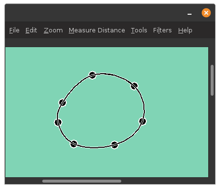
Spline Point(s). This option indicates that the
next point clicked will be a knot on a segment described by a
spline. The path will be a smooth path
going through each of the specified knots. While the spline is
actually a sequence of cubic Bézier curve segments, the
inner control points for those segments are not shown as these
are implicitly computed. Spline points are shown as solid
black circles with white borders. For example, the following
figure shows an EPTS window containing a closed curve
consisting of spline points (how to close a curve is described
below):
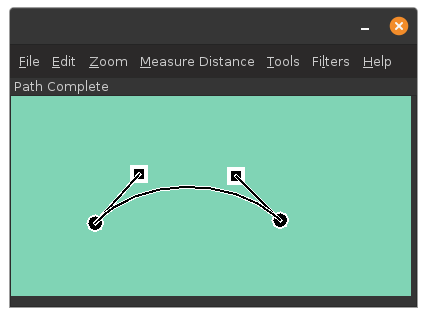
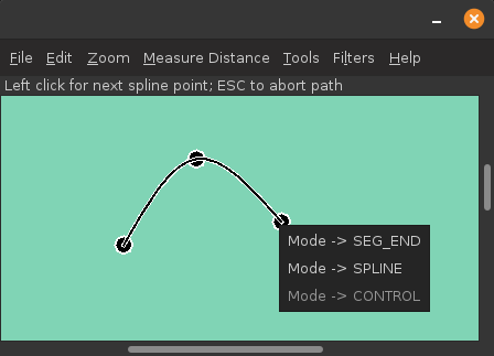
Control Point(s). This option indicates that
the next point is a control point. There can be at most two
control points in a row. Control points are as solid
black squares with white borders. For example, the following
figure shows an EPTS window containing an open curve with two
internal control points:
End Curve/Line
	Segment
. This option indicates that the next point
is the end of a segment. A segment with no intermediate
control or spline points is a
straight-line segment. Like spline points, the end-of-segment
points are shown as black circles with white borders.
Loop. The path will be closed by
connecting the last point entered to the first point on the
path. Loops containing only SPLINE points, aside
from its initial point, will create a spline that forms a loop
without any kinks. This is a special case, and it will not be
possible to change the type of a spline point to something
else. One can, however, select a node on the path and use a
pop-up menu item (accessible by clicking the right mouse
button) to break the loop. This will remove the segment connecting
the last point on the path to the initial point. One can then
change the type of points on the path as desired. Extending the
path will allow it be be closed again, but in this case, there may be
a kink at the starting point.
Path Ended. This option ends the current path
without closing it.
Get X-Y Coordinates (GCS). This menu item
will configure EPTS so that the X and Y coordinates of a point
(specified in GCS units), will be determined by clicking an
existing point. This can be used to arrange for lines to
meet at points with exactly the same coordinates. The existing
points are shown as filled circles (black surrounded by a white
ring). These points are not linked in any way so that transforming
one path will not transform another. This option can be used
when creating a path, or when a point on a path or a location has
been selected. When inserting a point before or after an existing
point on a path, this option affects the position of the new point.
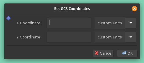
Set X-Y Coordinates (GCS). This menu item
will open a dialog box that will ask for the X and Y
coordinates of a point specified in GCS units:
Set/Move to current coordinates + (ΔX, ΔY) (GCS).
When creating a path, this option places the next point at the
GCS coordinates (X + ΔX, Y + ΔY) where (X, Y) is
the position of the current point. The type of the point is
determined by the current
Bézier-path option. If that
option is End Curve/Line Segment, then
this option can be used to add a vector specified using
Cartesian coordinates. Otherwise, if a point has been
selected, this option will move the point by incrementing its
X and Y coordinates by ΔX and ΔY
respectively. When inserting a point before or after an
existing point on a path, this option affects the position of
the new point.
Add Vector. This menu item will open a
dialog box that will ask for a length and an angle:
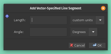
length field and
whose direction is given by the Angle
field. Both fields have adjacent pull-down menus that allow
units to be specified (distance units for the
length field and angular units
(degrees or radians) for the Angle field.
If there is a previous segment, the angle will be preset so
that the tangent at the end of the previous segment matches
the tangent for this segment. The angle can be changed if desired.
In cases where straight-line segments should be connected with
arcs whenever the direction changes, the preset angle will have
the desired value. This option always produces a straight-line
segment.
Add Arc. This menu
item will open a dialog box that will ask for a radius,
whether or not the kink angle should be measured from the
tangent to the curve or from the X axis, the kink angle (or
tangent angle for the first point on the curve), the angle
the arc subtends, and the angle direction (clockwise or
counterclockwise):
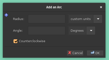
Radius field provides the radius of
the arc in GCS units.
Kink checkbox appears if the arc is not
at the start of a path and indicates if the kink angle
(described below) is relative to the tangent of the path
or the positive X axis. When present, the default is for
the checkbox to be unchecked.
Kink Angle field provides the angle in the
counterclockwise direction relative to either the tangent
of the existing portion of the path or the positive X axis
as determined by the preceding checkbox. This will be
labeled as the tangent angle from the X axis when the path
contains a single point. These angles are positive in the
counterclockwise direction.When left blank, this field
default to 0.
Angle field provides the angular
extent of the arc, with positive value indicating that the
arc's tangent at the current point is parallel to the
tangent vector at the current point and a negative value
indicating that the arc's tangent at the current point is
anti-parallel to the tangent vector at the current point.
Counterclockwise checkbox indicates
whether the arc, when the angle is positive, turns clockwise
or counterclockwise in graph coordinate space
(counterclockwise is defined as turning from the positive X
axis towards the positive Y axis). This checkbox determines
the position of the circle containing the arc regardless of
the sign of the angle. The arc accuracy can
be set in advance by using the
Set Arc-Angle Level menu item.
When the level is set to 1 (the default is 2), the maximum
angular extent for a cubic Bézier curve segment is 90
degrees. Increasing the arc level by 1 halves this angle.
Add points by running a command or opening a file.
This menu item opens a dialog box for obtaining points along a path
by running a command or reading from a file. In either case, the
data must be a CSV (Comma Separated Values) stream with three
fields:
MOVE_TO, SEG_END,
CONTROL, or SPLINE, but not
CLOSE.
MOVE_TO or SEG_END point. If the
CSV stream starts with a header, a dialog-box option will allow
that header to be skipped. The first data row in the CSV stream
must have a MOVE_TO type, and that type may not
appear anywhere else. The corresponding X and Y coordinates
are used directly to set the first point on the path when no
points have been entered. Otherwise the values are recorded,
and subtracted from the subsequent points, and these values
are treated as ones relative to the last existing point on
the path before the CSV points are read. There is
an example below.
Filter menu lets the user define filters that, when
applied, will configure which paths and locations are displayed.
Four menu items are always present:
New Filter. This option creates new filters.
Each filter has a name that will appear in the Filter menu below
the first two menu items.
Clear. This option turns filtering off.
Tranform Selectable Paths. For paths that
are selectable, the combined path will be used to find a center of mass
and principal axes, and an affine transformation will be applied to these
paths as specified by a dialog box, essentially a copy of the dialog
box provided by the Edit menu's
Transform an Existing PathNew Transformed Selectable Paths. When a
filter has been selected, the combined paths will be used to find
a center of mass and principal axes, and an affine transformation
will be applied to these paths as specified by a dialog box,
essentially a copy of the dialog box provided by the Edit menu's
New Transformed PathWhen a new filter is created or when an existing filter's menu item is clicked, a dialog box will appear that allows the filter to be configured. Both the filter as a whole and individual paths and locations provide a mode that determines how entries are filtered. The choices for a mode are the following:
Default. No changes are made for a path or location
Selectable. A path or location is marked as
selectable. When drawn, both paths and control points are drawn.
Drawable. Paths are drawn but control points are
not drawn.
Invisible. The path or location is not drawn.
Apply. The filter will be applied.
Save Only. The filter will be saved but not applied.
Delete. The filter will be deleted, thus removing
it from the Filter menu.
When a filter is applied, the mode for the filter as whole will first be
applied to each path and location. Then the modes for individual paths are
applied. Typically, most of the modes for individual paths and locations will
be set to Default, so that the filter's overall mode will be
used, and a few will be set to different values.
The modes are initially set to Default for individual
paths and locations. A filter's overall mode is initially set
to Invisible.
When a filter has been applied, the menu title will change from
Filters to *Filters*. Clearing
the filters will restore the title to Filters and
make all paths and locations selectable.
Help menu provides several ways of viewing a
manual. This menu contains the following items:
Manual. This option shows the manual in a window
that contains two panes: one with a table of contents and the
other with the manual itself.
Print Manual. This option opens a printer dialog
box and allows the user to produce a printed copy of the manual.
Browser. This option opens the system's
default browser and displays the manual in it. As a side effect,
an embedded web server will also be started, and that web server
can be accessed by other users. If the port number is not set or
is set to zero, the system will choose the port to use. For Firefox,
if NoScript is used, scripting must be enabled: otherwise the table
of contents will not be shown due to the use of XSL.
Port for Manual`s Webserver. When a TCP port
was not specified on the command line, this option gives the user
a chance to change the port number until the web server is started.
Start Manual's Webserver. This option starts
the web server used to show the on-line manual. While EPTS can display
the manual directly, a web server is useful when a nearby computer
can be used to display the manual and EPTS is not installed on that
computer. If the port number is set to 8080 the corresponding URL
will be <http://HOSTNAME.local:8080/>, where
HOSTNAME is the name of the computer on which EPTS is installed.
As a use case, suppose two people are in a coffee shop and are
using EPTS, which is installed on one computer. Starting the EPTS web
server will allow the manual to be displayed on the other computer
while the one on which EPTS is installed will be used to run the
EPTS application.
SEG_END, SPLINE, or CONTROL.
Only the options that are applicable given the types of the
previous points on the path will be enabled. For example:
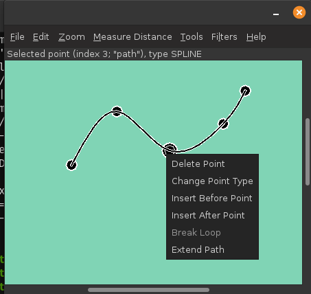
When a path is not being created or extended, but a point on a path has been selected, a popup menu is also available. This menu provides the following options:
Delete Point. This option deletes the selected point
from the path.
Change Point Type. This option allows one to change
the type of the selected point. The choice types is dependent on
the types of the surrounding points. If the path is closed and all the
intermediate points are spline points, the type of a selected point cannot
be changed. One can, however, break the loop and extend the path so that
the last point is a SEG_ENDpoint whose location is the
same as the initial point on the path.
Insert Before Point. This option allows one
to insert a new point into a path before the selected point. One
may click the mouse after moving it to the desired point, or one
may use one of the menu items in the Tools menu that will get or
set a point (these have the shortcuts G, P, and M).
Insert After Point. This option allows one
to insert a new point into a path after the selected point. One
may click the mouse after moving it to the desired point, or one
may use one of the menu items in the Tools menu that will get or
set a point (these have the shortcuts G, P, and M).
Break Loop. This option turns a closed path into an
open path. To close it again, first extend the path.
Append To Path. This option allows one to add new
points to a path. It will also re-order the table (for reasons
of convenience, when a path is extended, it is moved to the end
of the table). Existing specified points along the path (spline knots,
segment end points, and intermediate control points) will be displayed
using blue circles to distinguish these from newly added points.
This provides the same behavior as the Edit menu option
Append to a Bezier Path.
Extend Path. This option allows one to add
new points to a path. It will also re-order the table (for reasons
of convenience, when a path is extended, it is moved to the end of
the table). This provides the same behavior as
the Edit menu option Extend a Bezier Path.
epts extension) and for dialog
boxes used to set up saved-configuration files and template-processing
files (these have the eptc and eptt file-name
extensions respectively):
Zoom menu will list this
as Ctrl-Equals.
Undo Point Insertion or Move menu
item, whose shortcut is Control-Z, can be used to delete newly
added points, but not the existing ones shown in blue, nor the
path's initial point. Points can be added to the path, and the
path can be terminated, using the same operations used when a path
is newly created. For a closed path, the loop must be broken for
this shortcut to be used.
Undo Point Insertion or Move
menu item, whose shortcut is Control-Z, can be used to delete
points from the chosen path, starting at the end of the path.
path and ends with a positive integer. The
text field in the dialog box accepts parameters separated from the
variable name and each other by semicolons. Each parameter
consists of a key and a value, separated by an "=" symbol. Leading
and trailing whitespace is ignored for both keys and values. The
keys are any of the following:
Configure CGS menu item allows
graph coordinate space to be configured.
pt and ends with a positive integer. The
text field in the dialog box accepts parameters separated from the
variable name and each other by semicolons. Each parameter
consists of a key and a value, separated by an "=" symbol. Leading
and trailing whitespace is ignored for both keys and values. The
keys are any of the following:
By contrast, some key combinations apply only when a path or location exists:
Add Arc menu item from the
Tools menu.
Add Vector menu
item from the
Tools menu.
Append to a Bezier Path edit-menu item is used.
--template
command-line option. The value is either a URI or a file name.
There are a number of built-in templates that are accessible by
using a URI whose scheme is resource. These fit
into two categories: table templates and path-iterator templates.
Table templates represent paths as a series of points whose types
are MOVE_TO, CONTROL, SEG_END,
SPLINE, and CLOSE. Path-iterator templates
by contrast construct each spline along a path
and then represent the path as a sequence of SEG_CLOSE,
SEG_CUBICTO, SEG_LINETO,
SEG_MOVETO, or SEG_QUADTO segments, each
with 0 to 3 control points. The names for each type are the same as
the names of the corresponding java.awt.geom.PathIterator
constants.
To use a template, one must also specify an output file, which may be
done with the -o command-line option. EPTS will not
provide a GUI when templates are used with the -o
command-line option. If the argument to the -o option is
"-", the output will be sent to standard output. If the
-o is not provided and the argument file is an eptt file,
a GUI will be started to allow the eptt file to be edited. If the
-o is provided with an eptt file, the template
options will be recovered from the eptt file and the file
specified as the argument to the -o option will be used
as the output file. For this case, the eptt file must be in
the current working directory. In practice, this is typically the case
due to the use of tools such as make. For example, a makefile
may contain the rule
image.svg: image.epts image.eptt
        epts -o image.svg image.eptt
image.epts and can change the properties of paths such as
line colors by opening the file image.eptt.
resource. For convenience there is a shortcut: if
the templates option includes a colon followed by a template name,
a built-in template with that name will be used. For example,
andepts -o paths.js --template:ECMAScriptPaths saved.epts
are equivalent. Table templates by default will produce entries for all paths and locations. To restrict the paths or to use them in some specialized way, theepts -o paths.js --template resource:ECMAScriptPaths saved.epts
--tname command-line option can be used.
For example, if the saved.epts file in the example above includes
a path named firstPath and path named secondPath
in its table, the command
will include only these two paths in its output fileepts -o path.js --template:ECMAScriptPaths \ --tname firstPath -tname secondPath saved.epts
path.js.
The built-in table templates are the following:
resource:distances. This will print the
distances and corresponding path parameters for those points along
a path that are spline points or points on
segment boundaries. The path parameters are integer-valued, and
for the path parameter 0.0, the corresponding distance is always
zero. For paths that have subpaths, the distances and path
parameters are those appropriate for each subpath.
resource:ECMAScript. This will print the
information included in the EPTS table. Each path or location is
represented by an ESP or ECMAScript variable. For locations, the value
assigned to the variable is an object whose properties
x and y provide the coordinates of the
point. If there are no --tname options, all paths and
locations are included in the output; otherwise only the ones
specified by --tname options are included. For paths,
if stroke or color options are not used, the object will be an
array of objects, each describing a control point. In this case,
the value assigned to the variable will be an object that can be
used to configure an instance of
org.bzdev.geom.SplinePathBuilder. When the corresponding
--tname option's argument names a single EPTS path,
the array can also be used to configure an instance of
org.bzdev.anim2d.AnimationPath2DFactory or
org.bzdev.geom.BasicSplinePathBuilder. If a stroke or
color option is provided, the object will be an array of two
objects, where the first object describes a stroke, color, and
Z-order, and where the second object
contains an array of control points describing the path itself.
Because of the constraints imposed by the class
AnimationPath2DFactory the corresponding
--tname option must name a single EPTS path when a
stroke or color option is provided.
resource:ECMAScriptLayers. This option
will print the information included in the EPTS table. Each path
is represented by an ESP or ECMAScript variable. Location entries are
ignored. For the paths specified by --tname options,
or all paths if there are no --tname options, the
value assigned to each variable will be an array of objects. The
array can be used to configure an instance of
org.bzdev.anim2d.AnimationLayer2DFactory.
One may use the --tname option to include only
specific paths and optionally to use a new variable name that
represents a single path or the concatenation of multiple paths.
When a --tname option is used, a --winding-rule
option may be used, as can color or stroke options.
resource:EMCAScriptLocations.
This template provides the same ESP or ECMAScript statements that the
resource:ECMAScript template produces, but only
locations are included, not paths. For the locations specified by
the --tname options, or all locations if there are
no --tname options, the value assigned to each
variable will be an object specifying a location.
resource:ECMAScriptPaths.
This template provides the same ESP or ECMAScript statements that the
resource:ECMAScript template produces, but only
paths are included, not locations. For the paths specified
by --tname options, or all paths if there are
no --tname options, the value assigned to each
variable will be an array of objects. The array can be used to
configure a path using
org.bzdev.anim2d.AnimationPath2DFactory or
org.bzdev.geom.BasicSplinePathBuilder.
resource:JavaLocations. This template
provides a Java class containing fields that are instances of
the Java class java.awt.geom.Path2D with each field
named by the name provided in a --tname option. If
there are no --tname options, the field names are
the names of all the locations defined in the EPTS table. Multiple
--tname options are allowed.
resource:JavaPathBuilders. This template
provides a Java class containing fields that are instances of the
Java class
org.bzdev.geom.SplinePathBuilder with each field
named by the primary name (the name before a colon in the argument
for this --tname option) in a --tname
option for a path. If there are no --tname options,
the field names are the names of all the paths defined in the EPTS
table. A --winding-rule option preceding a
--tname option will configure a
winding rule for the corresponding
spline-path builder, but any stroke or color options will be
ignored.
resource:JavaPathFactories.
This template provides a Java class containing fields that are
instances of the Java interface
org.bzdev.obnaming.NamedObjectFactory.IndexedSetter
with each field named by the name provided by a
a --tname option for a path. If there are
no --tname options, the field names are the names of
all the paths defined in the EPTS table. The arguments to the
--tname options must be simple names that match the
names of paths defined in the EPTS table. For a specific
--tname option, color or stroke options can be specified
(these must precede the --tname option to which they
apply).
resource:YAMLLayers. This template creates
a YAML file with an "execute" property that provides a series of
ESP variable definitions corresponding to the variable definitions
created with the resource:ECMAScriptLayers
template.
resource:YAMLLocations. This template creates
a YAML file with an "execute" property that provides a series of
ESP variable definitions corresponding to the variable definitions
created with the resource:ECMAScriptLocations
template.
resource:YAMLPaths. This template creates
a YAML file with an "execute" property that provides a series of
ESP variable definitions corresponding to the variable definitions
created with the resource:ECMAScriptPath
template.
resource:YAML. This template creates
a YAML file with an "execute" property that provides a series of
ESP variable definitions corresponding to the variable definitions
created with the resource:ECMAScript
template.
resource:HTMLImageMap. This template creates
an HTML MAP element. Such elements must have a name to be useful.
The command-line option --mapName can be used to provide
this name, or the GUI can be used, in which case the entry will
appear in the Global Parameters tab.
The image map will consist of a sequence of
AREA elements, each indicated by an EPTS path with some variable
name. An AREA's SHAPE attribute will have the values
circle, rect, or poly, which will also be the
value of a variable name's
key parameter. When the key's
value is circle, rect, or poly, a
template-processor directive with the same name will also exist
(i.e., if the value of key is circle, then a
directive named circle with the value circle will
exist as well). An AREA's HREF attribute's value is the
value of the variable
name's link parameter, and
an AREA's ALT attribute's value is the value of the
variable name's descr
parameter.
How the path is drawn depends on the SHAPE attribute. For
pdata is a variable generated by using
a template and defining a path, then
will set the configuration to the value provided by the variable- create - var: path1 name: path1 factory: pathf configuration: = pdata
pdata.
The built-in path-iterator templates are
resource:area. This template requires the use of
a --pname option to specify a path name, or to create a
new path that is the concatenation of several existing paths. It
provides the area enclosed by the path; "NaN" if the path contains
any open segments. If the command was run with the
--gcs option, the units are graph-coordinate-space
units; otherwise they are user-space units.
resource:areaVars. This template requires the use of
a --pname option to specify a path name, or to create a
new path that is the concatenation of several existing paths. It
provides the area enclosed by the path; "NaN" if the path contains
any open segments. If the command was run with the
--gcs option, the units are graph-coordinate-space
units; otherwise they are user-space units. The output will be
formatted as one or more 'var' statements, with "_area" appended
to the name provided at the start of each --pname
option. The variables will be suitable for use by the scripting
languages ECMAScript and ESP.
resource:circumference. This template requires
the use of a --pname option to specify a path name, or
to create a new path that is the concatenation of several existing
paths. It provides the circumference the path; "NaN" if the path
contains any open segments. If the command was run with the
--gcs option, the units are graph-coordinate-space
units; otherwise they are user-space units.
resource:circumferenceVars. This template requires
the use of a --pname option to specify a path name, or
to create a new path that is the concatenation of several existing
paths. It provides the circumference the path; "NaN" if the path
contains any open segments. If the command was run with the
--gcs option, the units are graph-coordinate-space
units; otherwise they are user-space units. The output will be
formatted as one or more 'var' statements, with "_circumference"
appended to the name provided at the start of
each --pname option. The variables will be suitable
for use by the scripting languages ECMAScript and ESP.
resource:pathlength. This template requires
the use of a --pname option to specify a path name, or
to create a new path that is the concatenation of several existing
paths. It provides the length of the path (the sum of the lengths
of all its segments). If the command was run with the
--gcs option, the units are graph-coordinate-space
units; otherwise they are user-space units.
resource:pathlengthVars. This template requires
the use of a --pname option to specify a path name, or
to create a new path that is the concatenation of several existing
paths. It provides the length of the path (the sum of the lengths
of all its segments). If the command was run with the
--gcs option, the units are graph-coordinate-space
units; otherwise they are user-space units. The output will be
formatted as one or more 'var' statements, with "_length" appended
to the name provided at the start of each --pname
option. The variables will be suitable for use by the scripting
languages ECMAScript and ESP.
resource:SegmentsCSV.
This template requires the use of a
--pname option to specify a path name, or to create a
new path that is the concatenation of several existing paths. The
template will create its output in CSV (Comma Separated Values)
format, describing the specified path. The name of the path will
not appear in the output. The CSV values contain 7 columns, some
of which may be empty. The first is type,
whose value can be SEG_CLOSE, SEG_CUBICTO,
SEG_LINETO, SEG_MOVETO, or
SEG_QUADTO, matching names defined by the class
java.awt.geom.PathIterator. The remaining values are
x0, y0, x1, y1,
x2, and y2. The values for these are
numbers or empty strings.
--pname option is used (the last one
provided). Multiple --pname options are used, however,
with the --svg or --svg-mm option.
Templates specify an output format for points and paths using the
syntax specified by the Java
class org.bzdev.util.TemplateProcessor. Instances of
this class are constructed using a tree consisting of objects whose type
is org.bzdev.util.TemplateProcessor.KeyMap or
is org.bzdev.util.TemplateProcessor.KeyMapList. This
tree determines the directives a give template processor supports
and how those directives are used. Each value corresponding to a key
is either a string (java.lang.String), a KeyMap,
an array of KeyMap, or a KeyMapList. The
keys name directives. When a key's value is a string, the directive is
a simple directive. Otherwise it is an iterative directive. When the
value of an iterative directive is a single KeyMap, the
iteration occurs once and this can be used a conditional (provided
when the directive is defined and missing when it is not defined).
A template contains a mixture of text and directives stored in a text file. In a template, directives start with the sequence "$(" and end with a closing ")". A simple directive contains a variable name and its value is a string that provides text that will be substituted for the directive. For example, the directive "$(varname)" will be replaced by a string containing a variable name. The directive "$$" is replaced with a single dollar sign. An iterative directive consists of a name, a colon (":") and a second name. Its value is either a key map (in which case it is treated like a list with a single value, or a list or array providing key maps over which one iterates). A following simple directive containing the second name will then end the iterative block.
Directives can be globally defined or can be scoped to apply only within an iterative block. When blocks are nested and a directive is defined at multiple levels, the most recent definition is used. In the following description, we will frequently refer to a directive by the name of its key.
EPTS provides key maps appropriate for representing its table entries. for these tables, EPTS defines several global directives:
class. This is a global directive that provides
the simple name of a Java class. Unless documentation for a template
states otherwise, this is the class name for a single class being
defined.
hasPackage. This is an empty iterative directive.
When present, it will provide a single iteration and indicates that
the key package has a non-null value.
items. This is an iterative directive providing
a sequence of items described below
optSpace. This is a global directive that
expands to either an empty string or a single space As typically
used, it will appear after the directive public
appears. This is primarily used in templates as part of the sequence
"$(public)$(optSpace)", so that when public
is not defined, no text will be added, and when
public is defined, there will be space following the
public directive.
mapName is a global directive that is a
synonym for class: Both always have the same
value. mapName is provided because it is a more
mnemonic directive name for HTML image maps.
package. This is a global directive that provides
the fully qualified class name of a Java package. Unless
documentation for a template states otherwise, this is the name of
a package in which the template will define a single class whose
name is specified by a class directive.
packageDir. This is global directive that
has the same value as the package directive but with
each '.' replaced with '/'. It is not used by build-in
templates. One use is for templates that help create HTML image
maps for Javadoc comments, where a package name has to be replaced
with the corresponding directory path.
public. This is a global directive that
expands to either an empty string or to the string
"public". As typically used, it will appear before
the Java keyword class in code generated by a template.
The directive items, as mentioned above, is an iterative
directive. This directive iterates through a list, setting values for
the following directives:
varname. This is a simple directive defining
a variable name associated with a location or path.
index. An overall index. This value is
incremented for each line in the table.
vindex. An variable-name index. This value
is incremented whenever a variable name changes.
location. This is an iterative directive
that defines a specific, isolated point. While iterative, each
definition contains only a single point. Both
location and pathStatement will not
both be present at a specific iteration, although one of the
two will be present.
pathStatement. This is an iterative
directive that defines the control points for a path. While
iterative, each pathSegment definition contains a single key map
as its value. Both
location and pathStatement will not both
be present at a specific iteration, although one of the two will
be present.
will generate a list of variable names, one per line, for all the points and paths that are currently defined.$(items:endItems)$(varname) $(endItems)
The value for location is a key map containing
the following keys describing a point:
x. The X coordinate of the point in graph coordinate
space.
y. The Y coordinate of the point in graph coordinate
space.
xp. The X coordinate of the point in image space.
yp. The Y coordinate of the point in image space,
measured from top to bottom(the standard Java convention).
ixp. The X coordinate of the point in image space,
rounded to the nearest integer.
iyp. The Y coordinate of the point in image space,
measured from top to bottom (the standard Java convention), rounded to
the nearest integer.
ypr. The Y coordinate of the point in image space
measured from bottom to (the reverse of the standard Java convention,
following the convention used in mathematics instead).
Similarly, the value for pathStatement is a key map
containing the following directives:
draw. This directive has the value "true" or
"false". When true, a path's outline will be drawn. Otherwise, the
path's outline will not be drawn.
fill. This directive has the value "true" or
"false". When true, a path will be filled. Otherwise, the
path's outline will not be filled.
hasAttributesThis is an iterative directive
which will provide at most a single iteration. When present (i.e.,
when the iteration count is 1), the directives draw
and/or fill will have the value true,
and attributes defining colors or strokes will exist.
hasDashIncrement. This is an iterative directive
which will provide at most a single iteration. When present (i.e.,
when the iteration count is 1), there is a single directive:
dashIncrement, whose value is the length of a "-" or
" " in a dash pattern. The units are GCS units when
gcsMode is true and user-space units
when gcsMode is false or not defined.
hasDashPattern. This is an iterative directive
which will provide at most a single iteration. When present (i.e.,
when the iteration count is 1), there is a single directive:
dashPattern, whose value is a string consisting of
"-" and " " characters, starting with a "-". A
sequence of N "-" or N " " denotes
a dash or gap whose length is N multiplied by the dash
increment. The pattern created will be periodic.
hasDashPhase. This is an iterative directive
which will provide at most a single iteration. When present (i.e.,
when the iteration count is 1), there is a single directive:
dashPhase, whose value is the offset at which the dash/gap
pattern starts. The units are GCS units when
gcsMode is true and user-space units
when gcsMode is false or not defined.
hasDrawColor. This is an iterative directive
which will provide at most a single iteration. When present (i.e.,
when the iteration count is 1), there is a single directive:
drawColor, whose value is a CSS color specification that
indicates the color used when drawing paths.
hasFillColor. This is an iterative directive
which will provide at most a single iteration. When present (i.e.,
when the iteration count is 1), there is a single directive:
fillColor, whose value is a CSS color specification that
indicates the color used when filling paths.
hasGcsMode. This is an iterative directive
which will provide at most a single iteration. When present (i.e.,
when the iteration count is 1), there is a single directive:
gcsMode, whose value is "true" if
strokes are defined using GCS units, or "false" if
strokes are defined using user space or image space units.
hasMiterLimit. This is an iterative directive
which will provide at most a single iteration. When present (i.e.,
when the iteration count is 1), there is a single directive:
miterLimit>, whose value is the "limit to trim a
line join that has a JOIN_MITER decoration. A line join is trimmed
when the ratio of miter length to stroke width is greater than the
miter-limit value. The miter length is the diagonal length of the
miter, which is the distance between the inside corner and the
outside corner of the intersection. The smaller the angle formed
by two line segments, the longer the miter length and the sharper
the angle of intersection. The default miter-limit value of 10.0f
causes all angles less than 11 degrees to be trimmed. Trimming
miters converts the decoration of the line join to bevel." (The
quote is from the Java API documentation for the class
java.awt.BasicStroke.) When present, the minimum allowed
value for the miter limit is 1.0. The units are GCS units when
gcsMode is true and user-space units
when gcsMode is false or not defined.
hasStrokeCap. This is an iterative directive
which will provide at most a single iteration. When present (i.e.,
when the iteration count is 1), there is a single directive:
strokeCap, whose value is either BUTT,
ROUND, or SQUARE. The values defines the
type of decoration at the end of a line as described in the
documentation for the Java enumeration type
org.bzdev.obnaming.misc.BasicStrokeParm.Cap.
hasStrokeJoin. This is an iterative directive
which will provide at most a single iteration. When present (i.e.,
when the iteration count is 1), there is a single directive:
strokeJoin, whose value is either BEVEL,
MITER, or ROUND. These values define how
line segments are joined as described in the documentation for the
Java enumeration type
org.bzdev.obnaming.misc.BasicStrokeParm.Join.
hasStrokeWidth. This is an iterative directive
which will provide at most a single iteration. When present (i.e.,
when the iteration count is 1), there is a single directive:
strokeWidth, whose value is the width of a stroke used
to draw a path. The units are GCS units when
gcsMode is true and user-space units
when gcsMode is false or not defined.
hasWindingRule. This is an iterative directive
which will provide at most a single iteration. When present (i.e.,
when the iteration count is 1), there is a single directive:
windingRule, whose value is WIND_EVEN_ODD
or WIND_NON_ZERO.
hasZorder. This is an iterative directive
which will provide at most a single iteration. When present (i.e.,
when the iteration count is 1), there is a single directive:
zorder, whose value is a long integer.
pathItem. This is an iterative directive that
will list a series of objects representing a path.
pathItem directive contains the following
directives:
pindex. The value is "1" for the initial
MOVE_TO operation for a path and is incremented for
each control point, spline point, or
end-of-segment point, along the path, and for a final 'close'
directive if there is one.
type. This is the type of a point or operation
along the path (MOVE_TO, SPLINE,
CONTROL, SEG_END, or CLOSE).
ltype. This is similar to the type
directive, but substitutes CONTROL_POINT for
CONTROL, and SPLINE_POINT
for SPLINE. The directive ltype is useful
for configuring an instance of the class
org.bzdev.anim2d.AnimationLayer2DFactory.
atype. This is is similar to type but
with an alternative value defined by the user via a command-line
argument that provides the name of a file mapping types to their
replacement strings.
optcomma. This provides an optional comma that,
when used at the end of pathItem block, will result in
a comma being inserted as separator between items. If a different
separator a semicolon for example, is wanted one can use a construct
such as $(+optcomma:endOC);$(endOC), which will replace the comma with
a semicolon.
xy. This is an iterative directive, with 0 or 1
iterations. It defines the following directives (the same ones
as defined by the location directive) when the value of
typeis MOVE_TO, SPLINE,
CONTROL, or SEG_END:
x. The X coordinate of the point in graph
coordinate space.
y. The Y coordinate of the point in graph
coordinate space.
xp. The X coordinate of the point in image
space.
yp. The Y coordinate of the point in image
space, measured from top to bottom (the standard Java
convention).
ixp. The X coordinate of the point in image
space, rounded to the nearest integer.
iyp. The Y coordinate of the point in image
space, measured from top to bottom (the standard Java
convention) and rounded to the nearest integer.
ypr. The Y coordinate of the point in image
space measured from bottom to top (the reverse of the
standard Java convention, following the convention
used in mathematics instead).
dist. When set, this provides the
distance from the XY coordinates of the previous point to the
XY coordinates of this point in GCS units.
distp. When set, this provides the
distance from the XY coordinates of the previous point to the
XY coordinates of this point in image space units.
idistp. When set, this provides the
distance from the XY coordinates of the previous point to the
XY coordinates of this point in image space units, but rounded
to the nearest integer.
rad. When set, this provides the angle
a line from the point represented by the previous row's
XY coordinates to the point represented by this row's XY
coordinates makes with the positive X axis. Units are radians
with positive values in the counter-clockwise direction.
deg. When set, this provides the angle
a line from the point represented by the previous row's
XY coordinates to the point represented by this row's XY
coordinates makes with the positive X axis. Units are degrees
with positive values in the counter-clockwise direction.
radp. When set, this provides the angle
a line from the point represented by the previous row's
XY coordinates to the point represented by this row's XY
coordinates makes with the positive X axis. Units are radians
with positive values in the clockwise direction.
degp. When set, this provides the angle
a line from the point represented by the previous row's
XY coordinates to the point represented by this row's XY
coordinates makes with the positive X axis. Units are degrees
with positive values in the clockwise direction.
CLOSE, the xy directive
is not defined.
hasParameterInfo. This is an iterative
directive with 0 or 1 iterations. It will have a single iteration
when the type is MOVE_TO, SEG_END,
SPLINE, or CLOSE. An iteration defines
the following directives:
hasSubvarname. This is an iterative
directive with a 0 or 1 iterations. When it has 1 iteration,
the directive subvarname will be defined.
subpathvar. The name of a subpath,
if one exists. The iterative directive
hasSubpathvar can be used to test if this directive
is defined. For paths that are defined as a sequence of paths,
this variable names an individual path in that sequence.
s. The distance from the start of a subpath,
of the distance from the start of a path if there are no subpaths,
for the current point along a path.
u. The value of the path parameter for a
the subpath, or the path itself if the path does not have subpaths,
for the current point along a path.
For example, the following template will create a set of statements suitable for use by ESP or ECMAScript (the template EPTS actually uses has less whitespace so that the output will contain fewer blank lines and will be indented properly for readability):
  $(items:endItems)
     $(location:endLocation)
        var $(varname) = {x: $(x), y: $(y)};
  $(endLocation)
  $(pathStatement:endPathStatement)
     var $(varname) = [
         $(pathItem:endPathItem)
            {type: "$(type)"
            $(xy:endXY), x: $(x), y: $(y)$(endXY)}$(optcomma)
         $(endPathItem)
        ];
  $(endPathStatement)
$(endItems)
area. This directive contains the area of the
shape. If constructed from multiple paths, all of these paths must
be closed paths: otherwise the value will be "NaN". The units are
either user-space units or GCS units, depending on flags passed to
epts. When the epts command contains the
--gcs option, GCS units are used; otherwise
user-space units are used.
circumference. This directive contains the
circumference of the shape. If constructed from multiple paths,
all of these paths must be closed paths: otherwise the value will
be "NaN". The units are either user-space units or GCS units,
depending on flags passed to epts. When the
epts command contains the --gcs option,
GCS units are used; otherwise user-space units are used.
pathLength. This directive contains the path length
for the boundary of a shape, regardless of whether it encloses an
area. The units are either user-space units or GCS units,
depending on flags passed to epts. When the
epts command contains the --gcs option,
GCS units are used; otherwise user-space units are used.
varname. This directive provides the name of the
variable whose value is the path that the following directives
describe.
windingRule.
This directive determines the winding rule. Its values are
either WIND_EVEN_ODD or WIND_NON_ZERO.
WIND_EVEN_ODD indicates that a point is inside a
closed path if a ray drawn to infinity crosses path segments an
odd number of times. WIND_NON_ZERO indicates that a
point is inside a closed path if a ray drawn to infinity crosses
segments drawn in the counterclockwise direction a different
number of times than segments drawn in the clockwise direction.
segments.
This is an iterative directive that provides data for a sequence of
path segments. A MOVE_TO segment sets the current point
and the other path segments describe how to extend the path from
the current point.
segments directive:
type. This directive is always provided. Its value
can be either SEG_CLOSE, SEG_MOVETO,
SEG_CUBICTO, SEG_LINETO, or
SEG_QUADTO.
method. This directive is always provided. Its value
can be either closePath, moveTo,
lineTo, quadTo,or cubicTo.
These are the names of the Java methods used to construct a path.
hasClose. This is an iterative directive providing
0 or 1 iterations. When provided, it indicates that the path is to
be closed, terminating at the position give by the
last MOVETO operation. If necessary, a
straight-line segment will be added to close the path.
hasMoveTo. This is an iterative directive providing
0 or 1 iterations. When provided, it indicates that the path has
a section that starts at a specific point whose coordinates are the
values of the x0 and y0 directives.
hasLineTo. This is an iterative directive providing
0 or 1 iterations. When provided, it indicates that the current
segment is a straight line ending at a new current point whose
coordinates are given by the values of the x0
and y0 directives.
hasQuadTo. This is an iterative directive
providing 0 or 1 iterations. When provided, it indicates that the
current segment is a quadratic Bézier curve whose
first control point is given by the values of the x0
and y0 directives, and whose final point (the new
current point) is given by the values of the x1
and y1 directives.
hasCubicTo. This is an iterative directive
providing 0 or 1 iterations. When provided, it indicates that
current segment is a cubic Bézier curve whose first control
point is given by the values of the x0
and y0 directives, whose second control point is
given by the values of the x1 and y1
directives, and whose final point (the new current point) is given
by the values of the x2 and y2
directives.
x0. This directive, when present, gives the
X coordinate for a point that is either the starting point
provided for a SEG_MOVETO operation, the ending point
for a SEG_LINETO operation, or the first control
point for a SEG_QUADTO or SEG_CUBICTO
operation.
y0. This directive, when present, gives the Y
coordinate for a point that is either the starting point provided
for a SEG_MOVETO operation, the ending point for a
SEG_LINETO operation, or the first control point for a
SEG_QUADTO or SEG_CUBICTO operation.
x1 This directive, when present, gives the X
coordinate for a point that is either the final point for
a SEG_QUADTO operation of the second control point
for a SEG_CUBICTO operation.
y1. This directive, when present, gives the Y
coordinate for a point that is either the final point for
a SEG_QUADTO operation of the second control point
for a SEG_CUBICTO operation.
x2. This directive, when present, gives the X
coordinate for a point that is the final point for a
SEG_CUBICTO operation.
y2. This directive, when present, gives the Y
coordinate for a point that is the final point for a
SEG_CUBICTO operation.
hasClose, hasMoveTo, hasLineTo,
hasQuadTo, and hasCubicTo, one may use
the following directives:
has0 This is an iterative directive with 1
iteration that indicates that the directives x0
and y0 have non-empty values.
has1 This is an iterative directive with 1
iteration that indicates that the directives x1
and y1 have non-empty values.
has2 This is an iterative directive with 1
iteration that indicates that the directives x2
and y2 have non-empty values.
-o flag to set the
name of the output file, with a file name of - indicating
standard output. There are a large number of options, and some of the
GUI options can help manage these. A
few examples are shown immediately below,
followed by an examples section.
If the epts command is run with no arguments or only
--gui argument the, the program will open a dialog box
asking for the name of an image file to open, an EPTS saved state to
restore, or a script to run (which will use the default animation
name a2d) as described above.
To create a configuration file (the extension is "eptc"), one should
either use a desktop action or a command-line option shown below.
There are several combinations of command-line arguments that are treated specially:
--sessionConfig will open a dialog box that will
allow a session to be configured.
--templateConfig will open a dialog box that
will allow template processing to be configured.
--stackTrace --sessionConfig will open a dialog
box that will allow a session to be configured. Stack traces will
be included in various error messages.
--stackTrace --templateConfig will open a dialog box that
will allow template processing to be configured. Stack traces will
be included in various error messages.
--gui --stackTrace -- FILE will open the
specified file. This file may be a saved-state file
(extension epts), a session configuration file
(extension eptc), a script, or an image file. For some
error messages, a stack trace may be provided.
--gui --stackTrace with no additional arguments
will request an input file. This file may be a saved-state file
(extension epts), a session configuration file
(extension eptc), a script, or an image file. For
some error messages, a stack trace may be provided.
--gui -- FILE will open the
specified file. This file may be a saved-state file
(extension epts), a session configuration file
(extension eptc), a script, or an image file.
--gui with no additional arguments will open a dialog
box that will ask for a file to read. This file may be a saved-state
file (extension epts), a session configuration file
(extension eptc), a script, or an image file.
--stackTrace -- FILE will open an
input file, treating it specially if it is a session configuration
file. Some error messages will provide stack traces. The file can
be either a session configuration file, a saved-state file, an
image file, or a script.
--stackTrace will ask for a file to open. The file
can be either a session configuration file, a saved-state file, an
image file, or a script.p
-- FILE will open an input file,
treating it specially if it is a session configuration file. The
file can be either a session configuration file, a saved-state
file, an image file, or a script.
-o option and no
other options beside --, and --stackTrace.
-- before the file name so that file
names that start with "-" will not be confused with
options.
If the epts command is run with multiple file-name arguments, the program's behavior depends on the file format for the first argument:
epts", the state of a previous
session will be restored. Additional arguments are allowed, and
these must be script files. If the script files doe not have a
standard extension for a scripting language, the -L
option must be used to set the scripting language. The additional
scripts will not be kept if the state is saved. Instead, they
may be provided to enhance the current image. For example, the
script resource:grid.js will overlay an image with
a rectangular grid of lines. If the animation the script provides
is not stored in a variable named a2d, the
--animation option will also be needed.
Theepts image.png
# Configure GCS
# Save the session as (for example)saved.epts
epts --double spacing=10m saved.epts resource:grid.js
--double option is described below: it sets a
scripting-language variable to a specified value with optional unit
conversions. The URL scheme "resource" indicates that the script,
in this case grid.js is provided by EPTS. When a script
is added in this way, it augments the saved state temporarily, but
the script will not be added to the saved state if the saved state
is saved.
a2d" (the name can be different if
the --animation option is present). The animation will
not be run by epts, and should not be run by scripts. The
objects the animation initially creates will be used to generate
the image. If the animation the script provides
is not stored in a variable named a2d, the
--animation option will also be needed. In this case,
the scripts are saved if the session is saved. For example,
running
will restart EPTS and re-run the script.epts resource:grid.esp
# Use the "Save" option in the "File" menu # to create grid.epts
and then exitepts grid.epts
eptc
or eptt, it must be the only non-option argument. Either
can be proceeded by --gui, --stackTrace and/or
-- in that order (all are optional). For the eptt
case, this option may be proceeded by the arguments -o
OUTFILE, in which case a GUI will not appear, which is desirable
when the command is being run by software such as make that
tracks file dependencies.
file". Unless the first
file-name argument is a saved-state file, a new session will be
started and EPTS will ask for the name of a file when saving the
session's state. Usually a computer's window system will be configured
so that one can simply double-click the EPTS file rather than having
to run a specific command. For example the files
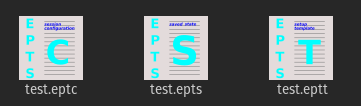
are EPTS saved-state files and restoring a session using these can be done using a computer's window system.
When run from the command line, a number of additional options are available. Specific categories of options are
scrunner program, whose configuration file
is used by EPTS.
There are five options that do not fit into well-defined categories:
--. This option simply indicates the end of
options, and is provided in case a file name starts with a
"-".
--image IFILE. This option implies
that a background image will be displayed. This option is not
needed unless IFILE is either - or a
saved-state file, but may be used to specify an image file if
desired (a URI referencing an image can be used as well). When
used with an image file, no arguments after the last option are
allowed. The most common image formats are PNG and JPEG. These
can use the file-name extensions "png" and "jpg" respectively. If
the file name is literally "-", EPTS will create an image
containing a solid background (the -w and
-h options can be used to set the image width and
height). The --animation option may not be used with
this option if IFILE is not an EPTS saved state.
When IFILE is an EPTS saved state for a saved state that is
the argument for an --image option, paths and
locations recorded in the saved state will be ignored, but additional
scripts can be added so as to be saved if a saved-state file is
created.
--port PORT. When this flag is used,
it sets the TCP port number for an embedded web server that will
provide the on-line manual. The port number PORT must be a
valid TCP port number (1 to 65535 inclusive, but some ports are
reserved or require system privileges). If the port is 0 or if
this option is not provided, the system will provide a port.
--animation A2D. This option
indicates that scripts will use the variable A2D to
store the animation used to reference an image. The
argument A2D is the name of a scripting-language variable
whose value will be an instance of the
class org.bzdev.anim2d.Animation2D. It will be used
to produce an image by creating a snapshot of the objects that are
currently defined in the animation and that are visible. The
scripts will configure this object. The constructor
for an Animation2D will determine the size of the image
unless the --image option is also present, but
the --image option can not be used with this option
unless the argument for --image is an EPTS saved state.
--gui. This option indicates that the program
might be run without directly starting the program from a terminal
window. The current working directory will be set to
that containing the file specified by the first non-option argument,
provided that the file is an image file or an EPTS saved state. In
addition, error messages (with a couple of exceptions) will appear
in windows rather than being printed to standard output. This is
provided because when a program is started using a window system,
the current working directory is often not the one containing its
argument file and messages to standard output or standard error
might not be visible to the user.
--sessionConfig. This argument is recognized if
it is the only argument used or if it is preceded by
the --stackTrace argument; otherwise an error will be
generated. It is intended for use by window systems for starting
EPTS in a particular mode. When this option is provided, EPTS
will first show the user a dialog box that allows the user to
provide data for various scripting-related arguments. The user
will be given an opportunity to save the configuration before
proceeding to run EPTS with the corresponding arguments.
nm for distances measured in nanometers.
um for distances measured in microns.
mm for distances measured in millimeters.
cm for distances measured in centimeters.
m for distances measured in meters (the conversion
factor is 1.0 in this case).
km for distances measured in kilometers.
in for distances measured in inches.
ft for distances measured in feet.
yd for distances measured in yards.
mi for distances measured in miles.
will show a script-generated image specified by saved.epts with its points and paths, and with a grid whose lines are spaced at 10-foot intervals in graph coordinate space in between.epts --double spacing=10ft saved.epts resource:grid.js
--boolean NAME=BVALUE. The
argument consists of two parts. NAME is the name of a
scripting-language variable and BVALUE is a boolean
represented by the value true or false
for that variable. The variable will be set before any script is
run.
--double NAME=DVALUE. The
argument consists of two parts. NAME is the name of a
scripting-language variable and DVALUE is a real number
that provides the corresponding value for that variable. The
variable will be set before any script is run.
--height HEIGHT. The height in points for
an image with one pixel per point that represents a drawing surface.
If not provided, a default of 1024 will be used.
--int NAME=IVALUE. The
argument consists of two parts. NAME is the name of a
scripting-language variable and IVALUE is an integer that
provides the corresponding value for that variable. The variable
will be set before any script is run.
--string NAME=SVALUE. The
argument consists of two parts. NAME is the name of a
scripting-language variable and SVALUE is a string that
provides the corresponding value for that variable. The variable
will be set before any script is run.
--width WIDTH. The width in points for
an image with one pixel per point that represents a drawing surface.
If not provided, a default of 1024 will be used.
scrunner options may also be appropriate for
scripting: the -L option allows the scripting language to
be explicitly configured (otherwise the language will be guessed from
file-name extensions), and the --codebase option will
allow other class libraries to be used in addition to the BZDev class
library that is loaded by default. For security reasons, a saved
state does not include the codebase: instead, the codebase must be
explicitly specified on the command line.
--class CLASSNAME.
This option applies when the --tname option is used,
and provides a class name for table templates that generate Java
code (e.g., a single Java class definition). The argument
CLASSNAME is the simple name for a class.
--elevate. This option applies when the
--pname option is set and is ignored otherwise. When
set, the degree of linear and quadratic Bézier curve
segments will be elevated so that all segments are cubic
Bézier curve segments.
--fill-color COLOR. This
option is used for table templates and applies to the path
specified by the following --tname option. It sets
the fill attribute to COLOR in an SVG path
and the parameter fillColor to COLOR as the
only element in a hasFillColor iterative parameter
for table templates. When used with animation-object factories,
it will determine if there is a drawColor.css
subparameter.
This option applies to a path specified by the
next --tname option. The value of COLOR can
be any color specification accepted by SVG (the same as those
defined by the CSS2 specification). A value of none indicates that
no color is specified and the path will not be drawn. Named colors
are listed at
<https://www.w3.org/TR/css-color-3/#svg-color>. A #
followed immediately by 6 hexadecimal digits gives the RGB values
(two hexadecimal digits each in that order). One can also use the
expression
rgb(R,G,B)
where the "red" component R , the green component G,
and the blue component B vary from 0 to 255 or 0% to 100%.
Similarly, the expression rbga(R,G,B,A)
can be used, where the alpha component A varies from 0 to 1
and the other components are the same as for the RGB case. An HSL (Hue,
Saturation, Lightness) specification can also be used:
hsl(H,S,L),
where H is a real number in the range [0, 360), S
is a real number in the range [0%, 100%], and L is a real
number in the range [0%, 100%]. With an alpha channel, the HSL syntax
is
hsla(H,S,L,A),
where A is a real number in the range [0, 1].
--flatness FLATNESS. This option
applies when the --pname option is set and is ignored
otherwise. When FLATNESS is zero,he --limit
option determines the number of times a segment will be
partitioned. Otherwise control points must deviate from a
straight line along each segment by at most the value
of FLATNESS.
--gcs. This option applies when the
--pname option is set and is ignored otherwise. When
present, it indicates that coordinates will be in GCS units. Otherwise
user-space or image space units are used.
--limit LIMIT.
This flag applies when the --pname
option is used and is ignored otherwise. This parameter limits the
amount of recursion used when paths are split to meet a flatness
criteria. When LIMITis zero, paths will not be partitioned.
Otherwise the path will be split recursively until the flatness limit
is reached, with LIMIT restricting the recursion depth.
--map MAPFILE.
The file MAPFILE is a text file (UTF-8 encoded) whose
entries are a series of lines. Each line contains a token
that is the name of an enumeration constant whose type is
org.bzdev.geom.SplinePathBuilder.CPointType, followed by
whitespace separating that token from its replacement value.
Any trailing whitespace will be removed from the replacement.
Valid token values are MOVE_TO, SPLINE,
CONTROL, SEG_END, or CLOSE.
In templates, the tokens become the value for $(type)
and the replacements become the value for $(atype).
If a mapping is not defined, the replacement is the same as the
original. The argument MAPFILE can be either a file
name or a URL. If the file named is a relative file, the name
is resolved using the current working directory when EPTS started.
This may not be the current working directory while EPTS is
running as the current working directory may be changed when an
EPTS file (one with a .epts extension) is processed. If
MAPFILE starts with the string "resource:",
"file:", "http:", "https:", or "ftp", then MAPFILE is
assumed to be a URL pointing to the object to read.
-o OUTFILE. This option
specifies the name of the output file for template processing. If
it is a relative file, it will be resolved against the current
working directory that existed when EPTS was started. If the file
name is "-", the output will be sent to standard output. When a
-o is present (it is required by the --svg,
--svg-mm, and --template options), there
must be a single filename argument: the name of an EPTS file
(e.g., saved.epts).
--package PACKAGENAME.
This option applies when the --tname option is used,
and provides a class name for table templates that generate Java
code (e.g., a single Java class definition). The argument
PACKAGENAME is the fully-qualified class name for a Java
package.
--pname PNAME. This option
selects a variable name, PNAME, that must match the name
of a path. It is used with templates that use the
path-iterator format. PNAME
may also consist of an identifier providing a variable name,
immediately followed by a ":", in turn followed by a series of
comma-separated path names. This in effect creates a path with a
new name that is a concatenation of paths specified in EPTS's
table. The main use of this variant is to create shapes that may
have holes in them. The options --elevate,
flatness, --gcs, limit,
and/or --straight may be used when a
--pname option is present. The options
--pname and --tname are mutually
exclusive.
--public. This option applies when the
--tname option is used and indicates that any Java
class being defined by a template should be a public class.
--straight. This option applies when the
--pname option is set and is ignored otherwise.
When set, the selected path will be flattened and converted to
straight-line segments.
--stroke-color COLOR. This
option is used for table templates and applies to the path
specified by the following --tname option. It sets the
stroke attribute to COLOR in an SVG path and
the drawColor parameter to COLOR as the
only element in a hasDrawColor iterative parameter
for use in table templates. Built-in templates that configure
animation-object factories use these to set
the drawColor.css subparameter.
This option applies to a path specified by the next --tname
option. The value of COLOR can be any color specification
accepted by SVG (the same as those defined by the CSS2
specification). A value of none indicates that no color is
specified and the path will not be drawn. Named colors are listed
at <https://www.w3.org/TR/css-color-3/#svg-color>.
A # followed immediately by 6 hexadecimal digits
gives the RGB values (two hexadecimal digits in that order). One
can also use the expression
rgb(R,G,B)
where the "red" component R , the green
component G, and the blue component B vary from
0 to 255 or 0% to 100%. Similarly, the expression
rbga(R,G,B,A)
can be used, where the alpha component A varies from 0 to 1
and the other components are the same as for the RGB case. An HSL (Hue,
Saturation, Lightness) specification can also be used:
hsl(H,S,L),
where H is a real number in the range [0, 360), S
is a real number in the range [0%, 100%], and L is a real
number in the range [0%, 100%]. With an alpha channel, the HSL syntax
is hsl(H,S,L,A), where A is a real number
in the range [0, 1].
--stroke-cap VALUE. This option is
used for table templates and applies to the path specified by the
following --tname option. Its values can be one of
the following: butt, which ends enclosed
subpaths and dash segments with no added decoration;
round, which ends enclosed subpaths
and dash segments with a round decoration that has a radius equal
to half the width of the stroke; and
square, which ends enclosed subpaths and dash
segments with a square projection that extends beyond the end of the
segment by a distance equal to half of the stroke width.
--stroke-dash-incr VALUE. This
option is used for table templates and applies to the path
specified by the following --tname option. The
argument VALUE is the length assigned to a "-"
or " " in a dash pattern. VALUE is specified
in graph coordinate space when the option --stroke-gcs-mode
is true; otherwise it is specified in user-space or
image space units.
--stroke-dash-pattern VALUE. A dash
pattern specifies how dashes are drawn. VALUE will be a
sequence of minus signs ("-") and spaces (" "),
starting with a "-". The length of N
"-" characters in a row or N spaces in a row
is N multiplied by the dash increment, and corresponds to
the length of a stroke or gap respectively. The dash pattern will
repeat. VALUE is specified in graph coordinate space
when the option --stroke-gcs-mode is
true; otherwise it is specified in user-space or
image space units. When provided, a dash pattern can consist
only of "-" characters and otherwise must start
with a "-" and end with a " ".
--stroke-dash-phase VALUE. This
option is used for table templates and applies to the path
specified by the following --tname
option. VALUE is offset to the start of the dash
pattern. VALUE is specified in graph coordinate space
when the option --stroke-gcs-mode is
true; otherwise it is specified in user-space or
image space units.
--stroke-gcs-mode BOOLEAN. This
option is used for table templates and applies to the path
specified by the following --tname option. The
value BOOLEAN can be true or
false. This option sets the
stroke.gcsMode subparameter for table templates, and
indicates if stroke dimensions are in GCS units or user-space
units (the default). For GCS units, the value must be true.
--stroke-join VALUE. This option
is used for table templates and applies to the path specified
by the following --tname option. Its values can be one of
the following:
bevel, which joins path segments by connecting
the outer corners of their wide outlines with a straight segment;
miter, which joins path segments by extending
their outside edges until they meet;
round, which joins path segments by rounding
off the corner at a radius of half the line width.
--stroke-miter-limit VALUE. This
option is used for table templates and applies to the path
specified by the following --tname option. The miter
limit is the limit such that a line join is trimmed when the ratio
of miter length to stroke width is greater than this value. The
miter length is the diagonal length of the miter, which is the
distance between the inside corner and the outside corner of the
intersection. The smaller the angle formed by two line segments,
the longer the miter length and the sharper the angle of
intersection. The default miter-limit value of 10.0 causes all
angles less than 11 degrees to be trimmed. Trimming miters
converts the decoration of the line join to a bevel. This value
applies only to a line join that has a miter join
decoration and must be larger than or equal to 1.0. VALUE
is specified in graph coordinate space when the
option --stroke-gcs-mode is true;
otherwise it is specified in user-space or image space units.
--stroke-width WIDTH. This
option is used for table templates and applies to the path
specified by the following
--tname option. It sets
the stroke-width attribute to WIDTH in an
SVG path. The value of WIDTH is
the width in graph coordinate space when the option
--stroke-gcs-mode is true; otherwise it is
the width in user-space or image space units.
--svg and --svg-mm.
Either of these options indicates that the output
will be an SVG (Scaleable Vector Graphics) file:
--svg is used for an SVG file in which
the image's width and height are in units of points (1/72
inches), the same units used in user space.
--svg-mm is used for an SVG file in
which the image's width and height are in units of millimeters
(mm). The width and height of the EPTS window, as viewed on a
screen, is scaled to the corresponding distance in graph
coordinate space, expressed in units of millimeters. For
example, if the height and width parameters when EPTS is
started are 1000, and graph coordinate space is configured so
that a distance of 5 in user space corresponds to 1 mm in
graph coordinate space, then the SVG image will have a
height and width of 200 mm. The --svg-mm option
is particularly useful when generating files for services
such as a laser-cutting service.
-o is required and at
least one --tname option should be present. The
options --fill-color, --stroke-color,
--stroke-cap, --stroke-dash-incr,
--stroke-dash-phase, --stroke-dash-pattern,
--stroke-gcs-mode, --stroke-miter-limit,
stroke-join, --stroke-width, and
--winding-rule, may be used (at least one will
typically be provided). A --template option must not
be provided.
--tdef
DEFNAME=DEFVALUE.
This option adds template key-value pairs for use by the template
processor in addition to the ones defined by EPTS. The argument
DEFVALUE is a string. If empty, the definition is ignored.
Otherwise, DEFNAME can be a name or a pair of names
separated by a colon. In the latter case, the first name in the pair
is treated as an iteration directive with a single iteration, mimicking
an 'if' statement, and the second name is the name to which the
value will be assigned. For example, the argument
--tdef hasCount:count=30 will result in the
template text
$(hasCount:endCount)count = $(count);$(endCount)
being changed into
count = 30--tdef
is present and into empty text when this --tdef is not
present. A number of names are reserved:
class, hasPackage, height,
items, optSpace, package,
paths, public, and width.
Some of these reserved names refer to iterative directives, and
each iterative directive will define additional directives during
an iteration. These will override a global directive with the same
name during an iteration but will not alter such a global
directive.
--template:RESOURCE.
This option is a shortcut that behaves like the option
--template resource:RESOURCE.
--template TFILE. This
option may not be used with the --svg option,
but as with the --svg option, the -o
option is required.
When TFILE starts with the string "resource:", "file:",
"http:", "https:", or "ftp", TFILE is assumed to be a
URL. Otherwise is is assumed to be the name of a file. The syntax
of a template is describe in the section of this manual entitled
"Templates". For the
resource protocol, the template is embedded in the
EPTS application. and these are described above in the section
describing built-in templates. The supported
table templates are resource:ECMAScriptLayers,
resource:ECMAScriptLocations,
resource:ECMAScriptPaths, and
resource:ECMAScript. These must be used without
the --pname option. Supported path-iterator templates
are resource:area, resource:areaVars,
resource:circumference,
resource:circumferenceVars
resource:pathlength, resource:pathlengthVars,
and resource:SegmentsCSV.<
These must be used with the --pname option.
--tname TNAME. This option's
argument TNAME provides the name of a variable that names
a path. When this option is provided, a table template must be
used and the keymap is the table keymap as described by the manual
page epts(5) and by the on-line manual for
epts. TNAME may be an existing identifier for
a path or a location in an EPTS table, or it may consist of an
identifier, immediately followed by a ":", in turn followed by a
series of comma-separated path names. This in effect creates a
path with a new name that is a concatenation of paths specified
in EPTS's table. Before each --tname option, there
may be a --winding-rule option. The options
--pname and --tname are mutually
exclusive.
--web. The --port option should
also be used to provide a non-zero port number. This option will
start an embedded web server allowing the manual to be shown.
--winding-rule RULE. This
option, when present, adds a winding
rule for use with table templates when
the --tnameoption is used, and must precede that
option. After a --tnameoption is seen, the winding
rule removed. The values of RULE may be
evenodd or nonzero. The
--winding-rule option sets a template-table keymap
directive as described in the documentation for
epts(5) and in the on-line manual.
--zorder VALUE. This option is
used for table templates and applies to the path specified by the
following --tname option. This option's argument
VALUE provides the Z-order for a path.
--. End of options. This can be used
if file names start with the character '-'. Otherwise
it is not necessary.
--add-modules SPEC. This
option's argument is a comma-separate list of module names.
Multiple instances of this option can be used as well. The list
must not contain whitespace. It is used primarily in cases in which
the only use of a module occurs in scripts. It is not necessary when
a module provides a factory as that is explicitly indicated in the
module definition.
--classpathCodebase SPEC. This
option's argument is treated the same of the argument for the
--codebase option below, but adds code bases to the
class path instead of the module path. This option is provided for
cases in which a JAR file cannot be used on the module path.
--codebase SPEC. This
option allows additional code bases to be available to the
JVM and places these on the module path. As a result, each codebase
must be a modular JAR file.
Any number of --codebase options may be
provided, and each option can contain multiple code bases with the
character '|' used as a separator. As a special case, if there are
n '|' characters in a row, they will be placed by
floor(n/2) '|' characters and when n is odd, the final
'|' is used as a separator. As a result, except for the
first component of a code-base path, components may not start with
a '|'. A code base is specified by either a URL or a path
name of a file in (local) file system. If there is a ':'
in the file name and the preceding characters are consistent with
a protocol name in a URL, the file name will be treated as a
URL. In this case, use a "file:" URL to specify the code base.
Several characters are treated specially. A leading "~" followed
by the name separator ("/" for Unix) is expanded to the user's
home directory. A file name consisting only of "~" is replaced
with the user's home directory. A leading "~~" is replaced
with "~", and a leading "..." followed by the name separator ("/"
for Unix) is replaced by the directory in which the BZDev class
library's JAR file is located. If an EPTS session is saved,
the saved file will contain the files and directories provided by
the --codebase options, but for security reasons the
user will be asked to confirm all codebases except those in the
same directory as the BZDev class library. Finally, the
substitutions for '|', '~', and '...'
(followed by the file-name separator) apply only to
the --codebase option, not to file-name arguments
that appear after the last option.
-DNAME=VALUE.
This option defines a system property whose name is NAME
and whose value is VALUE.
--dryrun. This options simply prints the java
command that will be used to start the JVM and run the program.
It is useful primarily for debugging.
-JOPTION. The string OPTION
is turned into an option passed to the 'java' command used
to start the JVM. It can be used, for example, to increase the
memory available to the JVM. If the option starts with a leading
'-', that must be provided explicitly.
-L LNAME.
When scripting is used, this option explicitly indicates a
scripting language. ESP (and currently
ECMAScript) are always supported.
--resourcePathNAMES. The string
NAMES is a series of URLS or file names separated by
the '|' character. As a special case, if there are
n '|' characters in a row, they will be placed by
floor(n/2) '|' characters and when n is odd, the final
'|' is used as a separator. As a result, except for the
first component of a code-base path, components may not start with
a '|'. If there is a ':'
in the file name and the preceding characters are consistent with
a protocol name in a URL, the file name will be treated as a
URL. In this case, use a "file:" URL to specify the resource.
In addition, if "~/" appears at the start of a file name, "~"
will be replaced with the user's home directory, a file
that is just "~" will be replaced with the user's home
directory, and a leading "~~" is replaced with one "~".
Multiple --resourcePath options can be used.
The following examples illustrate common cases.
epts saved.epts
epts tplate.eptt
epts saved.epts resource:grid.js
epts --double spacing=10ft --image s.epts
	resource:grid.js
saved.epts, but not restoring paths
and points created in previous sessions due to the presence of
the --image argument. The background image will
be augmented with additional scripts specified on the command
line, in this case the build-in script (grid.js) that
adds a grid overlaying the image. The grid spacing corresponds to
10 feet in graph coordinate space. If the session is saved, the
new saved-state file will include the previously defined scripts,
the new script defined on the command line, and the value for the
variable spacing (the value used is the distance in
meters corresponding to 10 feet).
epts --codebase foo.jar saved.epts
foo.jar to EPTS's code base.
epts image.png
epts --animation anim commands.js
anim (an instance of
org.bzdev.anim2d.Animation2D). In this case, a
saved-state file will rerun the script.
epts --resourcePath images commands.esp
a2d (an instance of
org.bzdev.anim2d.Animation2D). In this case, a
saved-state file will rerun the script. The --resourcePath
option allows external images to be included. For example, the
following ESP script
import(org.bzdev.anim2d, [
    Animation2D,
    AnimationLayer2D,
    AnimationLayer2DFactory]);

var frameWidth = 719;
var frameHeight = 375;

var a2d = new Animation2D(scripting,
                          frameWidth,
                          frameHeight,
                          1000.0, 40);
a2d.setRanges(0.0, 0.0, 0.0, 0.0,
              1.0, 1.0);

a2d.createFactories("org.bzdev.anim2d", {
    alf: "AnimationLayer2DFactory"});
###
alf.createObject("background", [
    {visible: true},
    {zorder: 0},
    {withPrefix: "object", withIndex: [
        {type: "IMAGE",
         imageURL:
             "resource:background.png",
         refPoint: "LOWER_LEFT",
         x: 0.0, y: 0.0,
         imageInGCS: false
        }
    ]}]);
background.png from the images
directory. Additional scripts such as resource:grid.esp
can be added as well.
epts --codebase foo.jar --animation anim commands.js
a2d (an instance of
org.bzdev.anim2d.Animation2D). The file foo.jar contains
additional classes needed by the script. The --codebase
option will be needed when restarting EPTS using a saved state
created when this command is being run.
epts -o out.js --template:ECMAScript saved.epts
out.js
containing a series of ESP or ECMAScript statements containing the contents
of the EPTS table.
epts -o out.svg --svg --fill red --pname s:c1,c2 saved.epts
out.svg
containing a shape sconsisting of two curves
(c1 and c2) defined in the EPTS table.
The table is the one defined by the file saved.epts
epts -o - --gcs --template:area -pname s:c1,c2
c1 and c2. The area is
in GCS units.
epts -o output.svg tplate.eptt
If scrunner has been installed, the following ESP script
(ESP is scrunner's default scripting language—a minimal
scripting language that uses the Java streams package for iteration)
will describe a path:
#!/usr/bin/scrunner -sE:true
import (org.bzdev.math.Functions);
import (org.bzdev.io.CSVWriter);

var w = new CSVWriter(global.getWriter(), 3);
var x0 = -15.0;
w.writeRow("MOVE_TO","" + x0, "" + 10*J(0, x0));

IntStream.rangeClosed(1, 100)
  .mapToDouble(function(i) {x0 + 0.3*i})
  .forEachOrdered(function(x) {
      w.writeRow("SPLINE", "" + x, "" + 10*J(0,x));
  });

w.flush();
w.close();
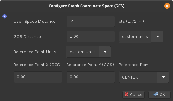
-sE:true on the first line of the script tells
scrunner that it can exit immediately after
the scripts are executed: there is no need to check for
any threads that might still be running.
A path generated by reading points from the script above is
shown in the following figure:
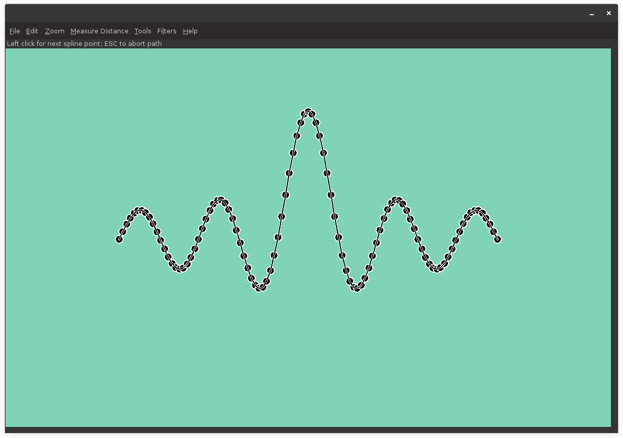
scrunner when the Java package
org.bzdev.anim2d is used. Some scripts require additional
code bases to run, in which case the --codebase option
will be needed. A copy of URLs indicating the codebase locations are
kept in saved-state file when scripts are used to create the
background image and the session is subsequently saved. Basically a
user will create an animation and a series of animation objects, but
will not actually run the animation. Initially, two variables are
defined. The first is named scripting and contains a
scripting context (the use of this is described in the BZDev class
library and scrunner documentation.) The second is the
variable epts, which is defined when EPTS is running. The
--animation option, when present, sets the name of the
scripting-language variable referring to the animation, with a default
variable name of "a2d". When a new script is run, EPTS
checks if the animation was created and if it is, EPTS will set the
variable a2d to refer to this animation (this is done so
because built-in scripts described below assume the animation is named
"a2d".
When image sizes are known and scripts are being
run, the scripting-language variable epts will have a
non-null value and will provide several methods:
epts.getWidth() to determine the frame width
in user-space units.
epts.getHeight() to determine the frame height
in user-space units.
epts.hasDistances() to determine if user-space
and graph-coordinate-space distances are valid (true if valid, false if
not).
epts.getUserDist() to determine a user-space
distance.
epts.getGCSDist() to determine a corresponding
graph-coordinate-space distance.
epts.getRefPointName() to determine location
of the reference point (the value is an enumeration constant defined
by org.bzdev.graphs.RefPointName.
epts.getXOrigin() to determine the X value in
graph coordinate space for the reference point.
epts.getYOrigin() to determine the Y value
in graph coordinate space for the reference point.
epts.getXFract() to determine the fractional
distance from the left edge of a graph's range to its right
edge. The values returned can be either 0.0, 0.5, or 1.0 and
match the RefPointName enumeration.
epts.getYFract() to determine the fractional
distance from the lower edge of a graph's range to its upper
edge. The values returned can be either 0.0, 0.5, or 1.0 and
match the RefPointName enumeration.
When there is no image, the variableif (typeof epts === 'undefined' || epts == null) { var frameWidth = 1024; var frameHeight = 1024; } else { var frameWidth = epts.getWidth(); var frameHeight = epts.getHeight(); } var a2d = new Animation2D(scripting, frameWidth, frameHeight);
epts will still be
defined, but its value will be null (when defined, that is an indication
that the script is being run by EPTS). While the
Configure CGS menu item will not be disabled
when there is no image, the fields shown in its dialog box will not
be editable.
After an animation is created, one will typically create animation
factories and use these factories to create animation objects that
can be displayed. In particular, animation layers can be used to
draw simple geometrical figures, figures based on paths, and can
scale and place images. The normal sequence of calling the animation's
methods initFrames, scheduleFrames and
run are skipped: EPTS will iterate through the
animation's objects using their Z-order and
write them to a graph, thereby creating a background.
To use EPTS in developing animations, one can use templates to
create ESP or ECMAScript code that will provide paths or in some cases
shapes. There will be a series of files that can then be
used by scrunner. Programs such as make
that track file dependencies can be used to run EPTS with template
options.
resource
protocol:
resource:grid.js overlays a rectilinear grid
as a representation of a Cartesian coordinates. The script uses
the ECMAScript scripting language.
resource:grid.esp overlays a rectilinear
grid as a representation of a Cartesian coordinates. The script
uses the ESP scripting language.
resource:polar.js overlays a polar grid as a
representation of polar coordinates. The script uses the
ECMAScript scripting language.
resource:polar.esp overlays a polar grid as
a representation of polar coordinates. The script uses the ESP
scripting language.
a2d, the scripts described below will not override that
value. They will, however, set the value of a2d if it is
null or undefined. EPTS itself will set a2d to the
current animation, if one exists, so that the built-in scripts use the
current animation (when available) instead of creating a new one.
If a2d is undefined or null, these scripts will create an
animation and assign it to a2d.
The grids the scripts display can be controlled by setting various EMCAScript variables. This is done using the CLI options
--boolean. This must be used for variables
whose values are either true or false.
--double. This must be used for variables
whose values are double-precision numbers
--int. This must be used for variables whose
values are integers (Java int or long
values).
--string. This must be used for variables
whose values are strings.
As stated in the Scripting Options
section of this manual, each of these options takes an argument of
the form VARIABLE=VALUE, where
VARIABLE is one of the variables listed the sections
describing Cartesian-grid scripts and
polar-grid scripts, and VALUE is the
corresponding value. The variables frameWidth,
frameHeight, userDist, gcsDist,
xorigin, yorigin, xfract,
and yfract are used by both scripts with the same
meaning. They are used by these scripts only if an animation has to
be created by them.
resource:grid.js
and resource:grid.esp will overlay an image with a
Cartesian (rectilinear) grid consisting of parallel, evenly spaced
lines in both the X and Y directions. The variables that configure
Cartesian grids are the following:
frameWidth—an integer giving the width of
the background image that will be created. The default is
1920. The value is ignored if the animation was created by another
script.
frameHeight—an integer giving the height
of the background image that will be created. The default is
1080. The value is ignored if the animation was created by another
script.
userdist—a double giving a reference
distance in user space. The default is 1.0. The ratio
userdist/gcsdist is the scaling factor for converting distances in
graph coordinate space to user space. The value is ignored if the
animation was created by another script.
gcsdist—a double giving a reference
distance in graph coordinate space. The default is 1.0. The ratio
userdist/gcsdist is the scaling factor for converting distances in
graph coordinate space to user space. The value is ignored if the
animation was created by another script.
xorigin—a double giving the X coordinate
in graph coordinate space for the frame's reference point. The
default is 0.0. The value is ignored if the animation was created
by another script.
yorigin—a double giving the Y coordinate
in graph coordinate space for the frame's reference point. The
default is 0.0. The value is ignored if the animation was created
by another script.
xfract—a double giving the fraction of the
frame width at which the reference point appears (0.0 is the left
edge and 1.0 is the right edge). The default is 0.0. The value is
ignored if the animation was created by another script.
yfract—a double giving the fraction of the
frame height at which the reference point appears (0.0 is the
lower edge and 1.0 is the upper edge). The default is 0.0. The
value is ignored if the animation was created by another script.
spacing—a double giving the grid spacing
in graph-coordinate space units. If not provided explicitly or if
the value is null, 0.0, or negative, the default is computed by
taking the minimum of the frame width and frame height, converting
that minimum to graph coordinate space units, then dividing by 10,
and finally finding the largest power of 10 that is not larger
than this value. The grid lines will appear at X or Y coordinates
that are an integral multiple of the spacing.
subspacing—the number of subspacings per
spacing for a finer grid. if undefined or 1, the value is
ignored. In practice, values that create a subgrid are either 2,
4, 5, or 10. The value must be an integer.
axisColor—the axis color provided as a CSS
string, null or undefined for the default.
spacingColor—the spacing color provided as
a CSS string, null or undefined for the default.
subspacingColor—the subspacing color
provided as a CSS string, null or undefined for the default.
strokeWidth—a double giving the width of
the stroke used to create grid lines; undefined or null for a
default.
gridZorder—an integer giving the
Z-order
to use for the object that creates the grid. The default is the
javascript value java.lang.Long.MAX_VALUE (253 - 1).
plainBackgroundColor—a string providing CSS
the color for the background when no image or animation is provided.
The default value is "white".
resource:polar.js and
resource:polar.esp will overlay an image with
a polar grid. These grids consist of a set of evenly spaced circles
centered at a common origin, and radial lines with the same angular
spacing, excluding areas near the origin where some lines may be
eliminated in order to prevent them from running together. The
variables that configure polar grids are the following:
frameWidth—an integer giving the width of
the background image that will be created. The default is
1920. The value is ignored if the animation was created by another
script. If undefined or null, the default will be used.
frameHeight—an integer giving the height
of the background image that will be created. The default is
1080. The value is ignored if the animation was created by another
script. If undefined or null, the default will be used.
userdist—a double giving a reference
distance in user space. The default is 1.0. The ratio
userdist/gcsdist is the scaling factor for converting distances in
graph coordinate space to user space. if undefined or null, the
default will be used.
gcsdist—a double giving a reference
distance in graph coordinate space. The default is 1.0. The ratio
userdist/gcsdist is the scaling factor for converting distances in
graph coordinate space to user space. If undefined or null, the
default will be used.
xorigin—a double giving the X coordinate
in graph coordinate space for a reference point in the frame. The
default is 0.0. The value is ignored if the animation was created
by another script. if undefined or null, the default will be used.
yorigin—a double giving the Y coordinate
in graph coordinate space for a reference point in the frame. The
default is 0.0. The value is ignored if the animation was created
by another script. If undefined or null, the default will be used.
xfract—a double giving the fraction of the
frame width at which the reference point appears (0.0 is the left
edge and 1.0 is the right edge). The default is 0.0. The value is
ignored if the animation was created by another script. If
undefined or null, the default will be used.
yfract—a double giving the fraction of the
frame height at which the reference point appears (0.0 is the
lower edge and 1.0 is the upper edge). The default is 0.0. The
value is ignored if the animation was created by another script.
If undefined or null, the default will be used.
fractional—true if the grid origin's
coordinates (gridXOrigin, gridYOrigin) are a fraction of the
position in the frame (excluding offsets); false if absolute
values in graph coordinate space are used. If undefined or null, a
default will be used.
gridXOrigin—a double giving the X
component of the grid's origin. When fractional is true, the
value is a fraction of the position in the frame, excluding
offsets, in the X direction. When false, it is the X coordinate of
the origin for a polar coordinate grid, given in
graph-coordinate-space units. If undefined or null, a default
value will be used.
gridXOrigin—a double giving the Y
component of the grid's origin. When fractional is true, the
value is a fraction of the position in the frame, excluding
offsets, in the Y direction. When false, it is the Y coordinate of
the origin for a polar coordinate grid, given in
graph-coordinate-space units. If undefined or null, a default
value will be used.
radialSpacing—a double giving the radial
spacing for concentric circles; null, undefined, 0.0 or negative
for a default.
angularSpacing—the angular spacing in
degrees for radial lines. The value should be a divisor of 90
degrees or either null or undefined for a default.
gridColor—the grid-line color provided as
a CSS string, undefined or null for the default.
strokeWidth—a double giving the width of
the stroke used to create grid lines; undefined or null for a
default.
gridZorder—an integer giving the
Z-order
to use for the object that creates the grid. The default is the
javascript value java.lang.Long.MAX_VALUE (253 - 1).
plainBackgroundColor—a string providing CSS
the color for the background when no image or animation is provided.
The default value is "white".
and ends with the line<?xml version="1.1" encoding="UTF-8"?> <!DOCTYPE images PUBLIC "-//BZDev//EPTS-1.0//EN" "resource:org/bzdev/epts/epts-1.0.dtd"> <epts xmlns="http://bzdev.org/DTD/epts-1.0">
The</epts>
resource protocol is one that is recognized by the
EPTS program and allows it to read the file epts-1.0.dtd
from the program's JAR file. The epts element contains a
sequence of elements:
image element.
codebase element.
modules element.
classpath element.
scripting element.
targetList element.
gcsconfig element.
table element.
filters element
image element does not contain any other
elements. Its attributes are
width. The value of this attribute is an
integer giving the width in pixels of an image that will be used
as a background.
height. The value of this attribute is an
integer giving the height in pixels of an image that will be used
as a background.
imageURIExists. The value of this attribute
is true or false. When
true, the following targetList
element will contain a single argument giving the URI for an image
to display. Otherwise the following targetList
arguments will contain the URIs for scripts that will be loaded.
If this attribute is missing, the default value is
false.
codebase element does not have any attributes.
Instead, it contains a sequence of path elements, which
also do not have any attributes. The contents of a path element
is text (XML PCDATA) providing a URI indicating where an image or
script can be found. Relative URIs will be resolved against the
URI for the current working directory.
moduleselement does not have any attributes.
Instead, it contains a sequence of moduleelements.
The contents of a module element is text (XML PCDATA)
providing the name of a module.
classpath element does not have any attributes.
Instead, it contains a sequence of path elements, which
also do not have any attributes. The contents of a path element
is text (XML PCDATA) providing a URI indicating where an image or
script can be found. Relative URIs will be resolved against the
URI for the current working directory.
scripting element has two attributes:
animation. The value of this attribute is the
name of a scripting-language variable that will be bound to an
instance of the class org.bzdev.anim2d.Animation2D
that will be used to create an image.
language. The value of this attribute is the
name of the scripting language (e.g., ESP or ECMAScript).
scripting element contains a series
of binding elements. These bind scripting-language variables
to values.
binding element has two attributes:
name. The value of this attributes is the name
of a scripting-language variable to which a value will be bound.
type. The value of this attribute provides the
Java type of a scripting-language variable, and can be
int for integer values, double
for real numbers, or String for strings.
java.lang.Integer.parseInt and for a real number,
the string must be usable as the argument of the method
java.lang.Double.parseDouble.
targetList element does not have any attributes. Its
contents consist of a sequence of argument elements.
The argument elements also do not have any attributes.
The content for each argument element is a URI for
a file. If a relative URI, it is resolved relative to the current
working directory (set when EPTS executes). If no protocol is provided,
the URI is assumed to be a file URI.
The protocol portion of the URL can contain the following:
file (a file on the local file system)
http (a resource obtained via an HTTP GET
request).
https (a resource obtained via a secure HTTP
GET request).
ftp (a resource obtained via FTP).
jar (an resource in a JAR file).
resource (a resource in the application's
code base).
gcsconfig element has the following attributes, all of
which are required except for unitIndexRP:
unitIndex. The value is an integer indicating
the type of units for GCS distances:
0. Distances are in custom units.
1. Distances are in nanometers (nm).
2. Distances are in micrometers (um).
3 Distances are in millimeters (mm).
4. Distances are in centimeters (cm).
5. Distances are in meters (m).
6. Distances are in kilometers (km).
7. Distances are in inches.
8. Distances are in feet.
9. Distances are in yards
10. Distances are in miles.
unitIndexRP. The value is an integer indicating
the type of units for reference-point X-Y coordinates:
0. Distances are in custom units.
1. Distances are in nanometers (nm).
2. Distances are in micrometers (um).
3 Distances are in millimeters (mm).
4. Distances are in centimeters (cm).
5. Distances are in meters (m).
6. Distances are in kilometers (km).
7. Distances are in inches.
8. Distances are in feet.
9. Distances are in yards
10. Distances are in miles.
refPointIndex. The value is an integer indicating
the reference point:
0. The reference point is at the
upper left corner of the image.
1. The reference point is at the
center of the upper edge of the image.
2. The reference point is at the
upper right corner of the image.
3. The reference point is at the
center of the left edge of the image.
4. The reference point is at the
center of the image.
5. The reference point is at the
center of the right edge of the image.
6. The reference point is at the
lower left corner of the image.
7. The reference point is at the
center of the lower edge of the image.
8. The reference point is at the
lower right corner of the image.
userSpaceDistance. A distance in user
space.
gcsDistance. A distance in graph coordinate
space corresponding to the user-space distance, measured in the
units specified by the unitIndex attribute.
xrefpointGCS. The X coordinate of the
reference point in graph coordinate space, given in the units
specified by the unitIndexRP attribute.
yrefpointGCS. The Y coordinate of the
reference point in graph coordinate space, given in the units
specified by the unitIndexRP attribute.
table element has no attributes and contains a sequence
of row elements. Each row element is empty, but
with the following attributes
varname. This attribute is present when the
type attribute has the value PATH_START.
Its value is the name of a variable. It should be one acceptable
to Java and to any scripting language that will be used.
type. This attribute is always present. Its
value can be one of the following:
LOCATION. The row represents a location.
The attributes x, y, xp, and
yp must be provided.
PATH_START. The row represents the start of
a path.
PATH_END. The row represents the end of a path.
MOVE_TO. The row represents a MOVE_TO operation.
The attributes x, y, xp, and
yp must be provided.
SPLINE. The row represents a knot on
a spline, excluding its end points.
The attributes x, y, xp,
and yp must be provided.
CONTROL. The row represents a control point.
The attributes x, y, xp, and
yp must be provided.
SEG_END. The row represents the end of a
segment
The attributes x, y, xp, and
yp must be provided.
CLOSE. The row indicates that the path
will be closed. A path is closed by drawing a straight line
segment from the last SEG_END point to the
first MOVE_TO point with one exception: if a path
starts with a MOVE_TO operation and otherwise
contains only SPLINE points, a
closed spline will be created.
x. The value of this attribute is an
X coordinate in graph-coordinate-space units (meters or custom units).
y. The value of this attribute is an
Y coordinate in graph-coordinate-space units (meters or custom units).
xp. The value of this attribute is the X
coordinate in user-space units, measured from the lower-left corner
of the image, with positive values pointing right.
yp. The value of this attribute is the Y
coordinate in user-space units, measured from the lower-left corner
of the image, with positive values pointing up.
The filters element does not have any attributes and just contains a possibly empty sequence of filter elements. Each filter element in turn contains a sequence of filterRow elements. A filter element has two attributes:
name. The value is a text string containing the
name of the corresponding filter.
mode. The value is one of the following:
DEFAULT. Do nothing.
SELECTABLE. Locations and paths are
selectable: they will be drawn and their control points will be
shown
DRAWABLE. Paths will be drawn but their
control points will not be shown.
INVISIBLE. Paths and locations will not be
drawn.
varname. The value is a text string containing
the name of a path or location.
mode. The mode for the corresponding path or
location:
DEFAULT. Do nothing.
SELECTABLE. The corresponding path or location
is selectable: it will be drawn and its control points will be
shown.
DRAWABLE. The corresponding path will
be drawn but its control points will not be shown.
INVISIBLE. The corresponding path or
location will not be drawn.
The offsets element does not have any attributes. It contains two other elements: an optional basemap element followed by an optional pathmap element. These two elements also do not have any attributes, and if neither is present, the offsets element is not needed. If there is a pathmap element, it must be preceded by a basemap element.
The basemap element contains a sequence of basemapEntry elements and does not contain any other elements. The attributes for the basemapEntry element are
base. This field provides a string naming
the base or reference path for an offset path.
mindex. An integer code indicating how an
offset path is to be generated. These codes are
0. The generated path is a closed path
with its distances from the reference path specified by
dist1 and dist2.
1. The generated path is an open path on
the counterclockwise side of the reference path with its
distance from the reference path specified by
dist3. The corresponding tangent vectors
are parallel to each other.
2. The generated path is an open path
on the counterclockwise side of the reference path
with its distance from the reference path specified by
dist3. The corresponding tangent vectors
are antiparallel to each other.
3. The generated path is an open path
on the clockwise side of the reference path
with its distance from the reference path specified by
dist3. The corresponding tangent vectors
are parallel to each other.
4. The generated path is an open path
on the clockwise side of the reference path with its distance
from the reference path specified by
dist3. The corresponding tangent vectors
are antiparallel to each other.
dist1. The distance from the reference
path in the counterclockwise direction to an offset curve that
contains segments on both sides of the reference path.
dist2. The distance from the reference path
in the clockwise direction to an offset curve that contains
segments on both sides of the reference path.
dist3. The distance from the reference path
to a single offset path.
uindex1. A code providing the units for the
dist1 attribute (see below for a description of these codes).
uindex2. A code providing the units for the
dist2 attribute (see below for a description of these codes).
uindex3. A code providing the units for the
dist3 attribute (see below for a description of these codes).
0. Distances are in custom units.
1. Distances are in nanometers (nm).
2. Distances are in micrometers (um).
3 Distances are in millimeters (mm).
4. Distances are in centimeters (cm).
5. Distances are in meters (m).
6. Distances are in kilometers (km).
7. Distances are in inches.
8. Distances are in feet.
9. Distances are in yards
10. Distances are in miles.
The pathmap element contains a sequence of pathmapEntry elements and does not contain any other elements. The attributes for the basemapEntry element are
path. This attribute contains the name of
an offset path.
base. This attribute contains name of
the base or reference path associated with the offset path.
org.bzdev.io.ZipDocFile: essentially a zip file
with an embedded media type and zip entries that are XML-encoded
using the Java method java.beans.XMLEncoder:
application/vnd.bzdev.epts-config+zip.
inputfile contains an XML-encoded
String providing a file name.
imageFlag contains an XML-encoded
Booleanindicating if EPTS should be started using an
--image argument.
animation contains an XML-encoded
String giving the name of the scripting-language variable
whose value will be an instance of org.bzdev.anim2d.Animation
after scripts are run.
scriptingLang contains an XML-encoded
String providing the name of
the scripting language in use, with the name (DEFAULT)
used to indicate the default language.
joptions contains an XML-encoded
object that is equal to the value returned by the
getDataVector method of DefaultTableModel
for a table containing options for the command java.
codebase contains an XML-encoded
object that is equal to the value returned by the
getDataVector method of DefaultTableModel
for a table containing additional codebases that will be placed on
the module path.
modules contains an XML-encoded
object that is equal to the value returned by the
getDataVector method of DefaultTableModel
for a table containing the names of additional modules.
classpath contains an XML-encoded
object that is equal to the value returned by the
getDataVector method of DefaultTableModel
for a table containing additional codebases that will be placed on
the class path.
scripts contains an XML-encoded
object that is equal to the value returned by the
getDataVector method of DefaultTableModel
for a table containing the path names or URLS for scripts that should
be executed.
variables contains an XML-encoded
object that is equal to the value returned by the
getDataVector method of DefaultTableModel
for a table specifying variables and their values. Each row of
this table consists of four columns:
eptc
in order to be recognized by the epts command.
org.bzdev.io.ZipDocFile, using Java method
java.beans.XMLEncoder to encode each zip-file entry:
application/vnd.bzdev.epts-template-config+zip.
basicData contains an XML-encoded
TemplateSetup.BasicData object. The inner class
BasicData is defined as follows:
The fieldpublic static class BasicData { public int templateTypeInd = -1; public boolean useBuiltins = false; public String template = null; public String savedState = null; public String mapName = null; }
templateTypeInd sets the selected index of
a javax.swing.JComboBox whose values are "SVG",
"Table Template", or "PI Template". The field useBuiltins
sets the state of a check box indicating if a "choose" button should
pick a builtin template or a template stored in an external file.
The Strings template, savedState, and
mapName are the names of the files or URLs provided by
the --template option, the first file-name argument,
of the --map option respectively.
tdefTable contains an XML-encoded
java.util.Vector, each of whose elements are instances
of java.util.Vector with three elements, all instances of
java.lang.String. Of these three elements, the first
names an iterative directive with a single iteration, the second
names a directive that will be defined, and the third provides a value for
that directive. Each of these
is used to generate a --tdef option. If the
iterative directive is TEST, the directive is
VAR, and the value is VAL, then
--tdef option is
--tdef
TEST:VAR=VAL
--tdef
option is
--tdef VAR=VAL
--tdef
option is --tdef TEST.
pathmap contains an XML-encoded
TemplateSetup.PathMap object. The inner class
PathMap is defined as follows:
This table is used to generatepublic static class PathMap extends LinkedHashMap<String,Vector<String>> { public PathMap() {super();} }
--tname and
--pname options for the case in which a path is
defined as a concatenation of paths in the EPTS table. The key is
the name of the new path and the corresponding value is a
java.util.Vector whose type parameter is String
and whose elements are the names of the path to concatenate.
globalData contains an XML-encoded
TemplateSetup.GlobalData object. The inner class
GlobalData is defined as follows:
The fieldpublic static class GlobalData { public boolean usesTableTemplate; // Table Template options public String packageName; public String className; public boolean isPublic; // Path-Iterator Template (--pname) options public FlatnessMode fmode = FlatnessMode.NORMAL; public double flatness; public int limit = 10; public boolean gcs; }
usesTableTemplate is true if options for
table templates should be generated and false if options for path
templates should be generated. The field packageName
is the argument for a --package option; the
field --className is the argument for
a --class option; the field flatness is
the argument for a --flatness option; and the
field limit is the argument fora --limit
option. When the field isPublic has the value
true, a --public option may be generated,
and when the field gcs has the value
true, a --gcs option may be generated.
Finally, the field fmode can have the values
TemplateSetup.FlatnessMode.NORMAL,
TemplateSetup.FlatnessMode.STRAIGHT, or
TemplateSetup.FlatnessMode.ELEVATED, with the last
two implying the options --straight and
--elevate respectively.
pathLocMap contains an XML-encoded
TemplateSetup.PathLocMap object. The inner class
PathLocMap is defined as follows:
where the inner classpublic static class PathLocMap extends TreeMap<String,PathLocInfo> { public PathLocMap() {super();} }
TemplateSetup.PathLocInfo is defined by
This table sets parameters associated with paths and locations, including paths that are defined in the PathMap table. The entries are ignored if the fieldspublic static class PathLocInfo { public boolean isPath; public boolean active = false; public double strokeWidth = 1.0; public boolean strokeGCS = false; public boolean draw = false; public Color drawColor = Color.BLACK; public boolean fill = false; public Color fillColor = Color.BLACK; public int capIndex = 0; public double dashIncr = 10.0; public String dashPattern = "-"; public double dashPhase = 0.0; public int joinIndex = 0; public double miterLimit = 10.0; public int windingRuleInd = 0; public long zorder = 0; public PathLocInfo() {isPath = false;} public PathLocInfo(boolean isPath) { this.isPath = isPath; }
isPath and
active are both false.
The field strokeWdith determines the value of
the --stroke-width option; the field
strokeGCS determines the value of the
--stroke-gcs-mode option; the
field drawColor determines the value of
the --stroke-color option; the
field fillColor determines the value of
the --fill-color option; the
field capIndex determines the value of
the --stroke-cap option; the
field dashIncr determines the value of
the --stroke-dash-incr option; the
field dashIncr determines the value of
the --stroke-dash-incr option; the
field dashPattern determines the value of
the --stroke-dash-pattern option; the
field dashPhase determines the value of
the --stroke-dash-phase option; the
field joinIndex determines the value of
the --stroke-join option; the
field windingRuleInd determines the value of
the --winding-rule option; and the
field zorder determines the value of
the --zorder option. The field --draw
must have a value of true for stroke-related options
to be used. Similarly the field --fill must have the
value true for the fill-color option to be used.
The values of the field capIndex indicate a value
from the sequence butt, round, and
square, with 0 indicating the first, 1 indicating the
second, and 2 representing the last of this sequence. Finally,
the values of the field joinIndex indicate a value
from the sequence bevel, miter, and
round, with 0 indicating the first, 1 indicating
the second, and 2 representing the last of this sequence.
outfile contains an XML-encoded
String giving an output-file name (an empty string if there
is no output file specified), and may be overridden by a command-line
option.
/usr/share/doc/libbzdev-doc/api/index.html.
The web page for the API documentation for the BZDev class library.
A link on this page provides a description of the ESP scripting language.
/usr/share/doc/libbzdev-doc/factories-api/index.html.
The web page for the BZDev class library's factories and their
parameters. This is usually sufficient for determining how to to
configure a factory.